Heat-storage power generation system

A power generation system and heat storage technology, which is applied to machines/engines, steam engine installations, steam applications, etc., and can solve the problems of high wind abandonment rate, deep peak shaving of cogeneration units, and poor thermal and electro-decoupling capability. Realize the effect of load shedding peak regulation and frequency regulation and increase load peak regulation and frequency regulation

Pending Publication Date: 2019-01-01
HEPU ENERGY ENVIRONMENTAL TECHNOLOGY CO LTD
View PDF5 Cites 3 Cited by
  • Summary
  • Abstract
  • Description
  • Claims
  • Application Information

AI Technical Summary

Problems solved by technology

[0008] The purpose of the present invention is to provide a heat storage power generation system, by setting a steam tank group to store the steam extracted from the main steam boiler or the main steam turbine or the steam generated by the electric steam boiler and use it for staggered power generation and / or for heat supply, It solves the technical problems of the high rate of abandoned wind and the deep peak regulation and poor thermoelectric decoupling ability of the combined heat and power unit in the existing technology

Method used


Image

  • Heat-storage power generation system
  • Heat-storage power generation system
  • Heat-storage power generation system

Examples


Embodiment 1

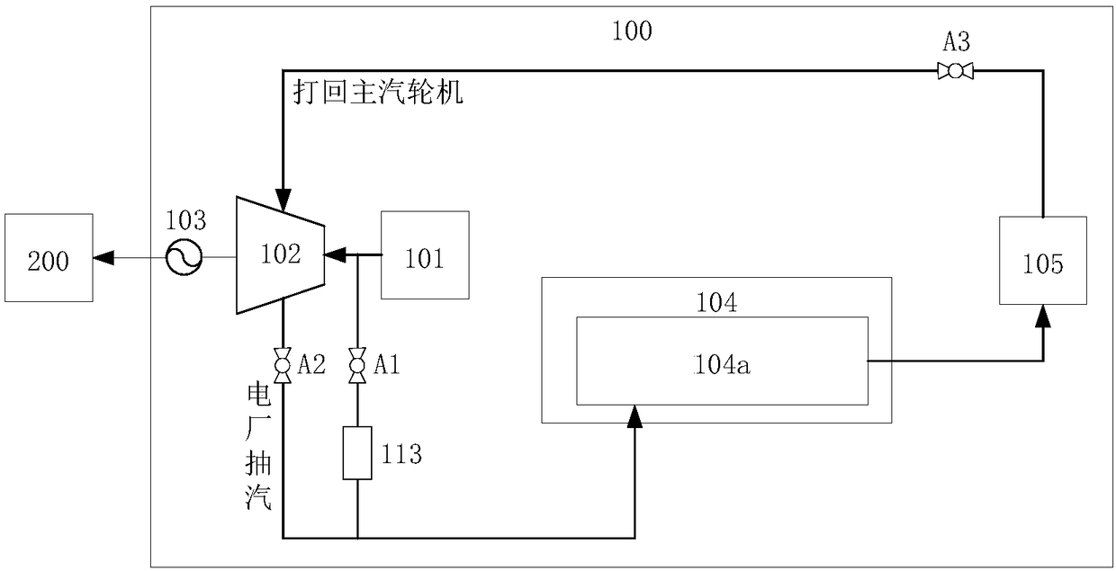
[0037] figure 1 It is a schematic composition diagram of the thermal storage power generation system provided by Embodiment 1 of the present invention.

[0038] Please refer to figure 1 , the present embodiment provides a thermal storage power generation system 100 , including: a main steam boiler 101 , a main steam turbine 102 , a main generator 103 and a steam tank group 104 .

[0039] The main steam boiler 101 is set in the power plant and used to generate steam.

[0040] The main steam turbine 102, the inlet of which communicates with the outlet of the main steam boiler 101, is used to convert steam energy into mechanical energy.

[0041] The main generator 103 is power-connected with the main steam turbine 102 and is used to convert mechanical energy into electrical energy driven by the main steam turbine 102 to supply power to the grid 200 .

[0042] The steam tank group 104 is provided with at least one high-pressure tank 104a, the inlet of the high-pressure tank 104...

Embodiment 2

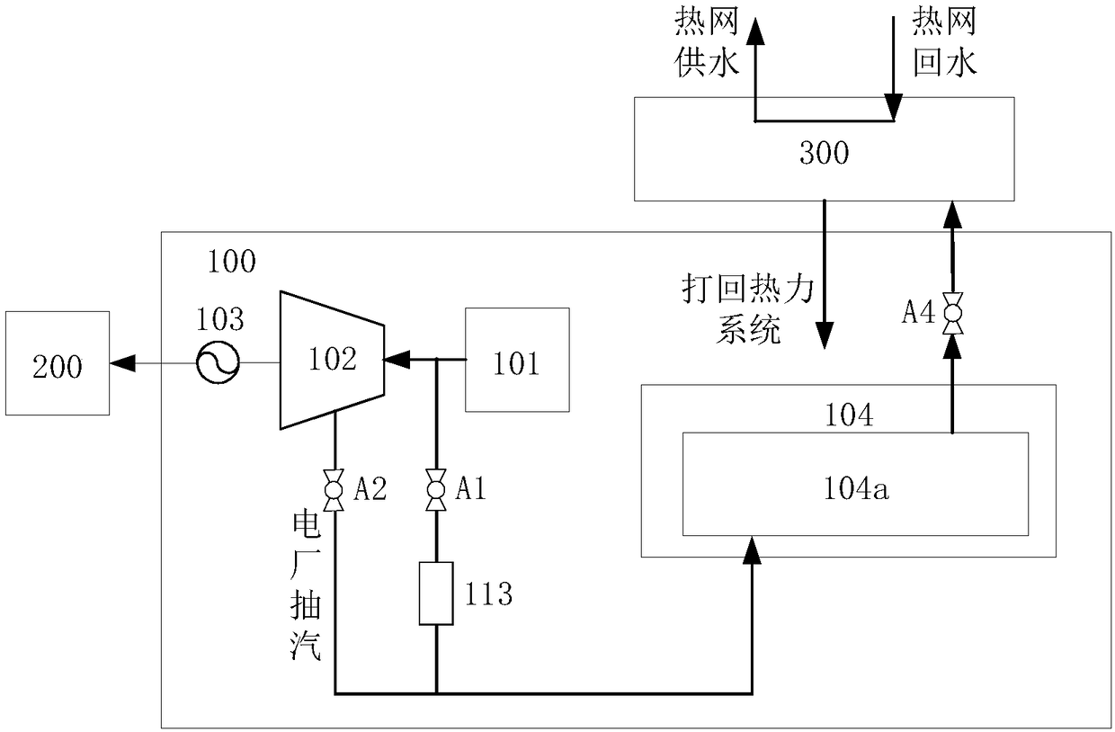
[0061] figure 2 It is a schematic composition diagram of the thermal storage power generation system provided by the second embodiment of the present invention.

[0062] The difference between this embodiment and Embodiment 1 is that the steam stored in the high-pressure tank 104a in this embodiment is used for heating.

[0063] Please refer to figure 2 , in this embodiment, the outlet of the high-pressure tank 104a is connected to the heat network heat exchanger 300, and the steam stored in the high-pressure tank 104a is exchanged with the heat network through the heat network heat exchanger 300 for heat supply.

[0064] Specifically, the outlet of the high-pressure tank 104a is connected to the heat network heat exchanger 300, so that the steam stored in the high-pressure tank 104a is introduced into the heat network heat exchanger 300 for heat exchange for heat supply. After the heat exchange, the steam is condensed into water and Call back the thermal system of the mai...

Embodiment 3

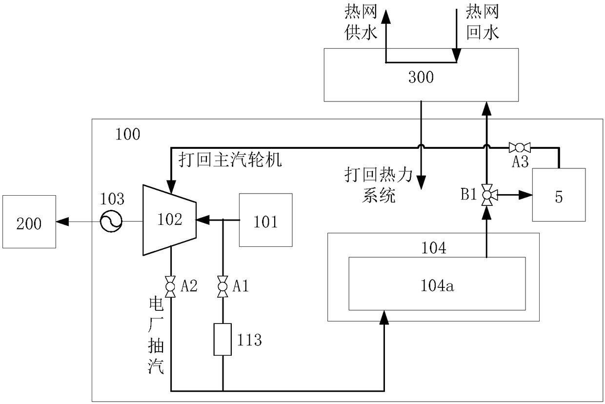
[0077] image 3 It is a schematic composition diagram of the heat storage power generation system provided by Embodiment 3 of the present invention.

[0078] Please refer to image 3 , the thermal storage power generation system 100 in this embodiment is a combination of Embodiment 1 and Embodiment 2, and the two-way valve A4 in Embodiment 2 is replaced by a three-way valve B1.

[0079] In this embodiment, the three-way valve B1 is arranged at the outlet of the high-pressure tank 104a, and is used to divide the outlet of the high-pressure tank 104a into two paths, and one path is connected to the main steam turbine 102 through the first electric superheater 105, so that the high-pressure tank 104a The stored steam is used for power generation at different times, for load-increasing peak-shaving and frequency regulation, and another path is connected to the heat network heat exchanger 300 to introduce the steam stored in the high-pressure tank 104a into the heat network heat e...


PUM


Abstract

The invention discloses a heat-storage power generation system, and belongs to the technical field of thermoelectricity. The heat-storage power generation system comprises a main steam boiler (101), amain steam turbine (102), a main power generator (103) and a steam tank group (104), wherein the main steam boiler is used for generating steam; the inlet of the main steam turbine communicates withthe outlet of the main steam boiler (101); the main steam turbine is used for converting steam energy into mechanical energy; the main power generator is used for converting mechanical energy into electric energy and supplying power to a power grid (200); the steam tank group is equipped with at least one high-pressure tank (104a); the inlet of the steam tank group communicates with the outlet ofthe main steam boiler (101) and/or a steam extraction port of the main steam turbine (102); and the steam tank group is used for storing steam extracted from the main steam boiler (101) and/or the main steam turbine (102), so that load-shedding peak load regulation and frequency regulation can be achieved, and the stored steam can be used for the load-increasing peak load regulation and frequencyregulation during staggered power generation and/or used for heat supply. The heat-storage power generation system disclosed by the invention has the beneficial effect that through the arrangement ofthe steam tank group, the steam generated from the main steam boiler can be extracted for being stored, the stored steam can be used for staggered power generation, and then load-shedding and load-increasing peak load regulation and frequency regulation in the heat-storage power generation system can be quickly achieved.

Description

technical field [0001] The invention relates to the technical field of thermoelectricity, in particular to a thermal storage power generation system. Background technique [0002] In recent years, with the rapid development of China's national economy, people's demand for electricity has also increased sharply, and the peak-to-valley difference has increased day by day. The peak-to-valley ratio of China's power supply is about 10 / 0.7, much higher than the average level of 1 / 0.63 in developing countries, and much higher than the peak-to-valley ratio of 1 / 0.25 in the United States. Therefore, the task of peak regulation and frequency regulation of China's generating units is arduous. The peak-shaving and frequency-regulating capability of the generator set is the first important barrier to maintain the power balance, safety and stability of the power grid. Its adjustment capability and performance are particularly important for the dynamic stability of the power grid; The sel...

Claims


Application Information

Patent Timeline
Patent Type & Authority Applications(China)
IPC IPC(8): F01K3/06F01K3/14F01K3/12F01K11/02F01K17/02F01D15/10
CPCF01D15/10F01K3/06F01K3/12F01K3/14F01K11/02F01K17/02
Inventor 崔华杨豫森徐波谭智陈辉
Owner HEPU ENERGY ENVIRONMENTAL TECHNOLOGY CO LTD
Why Eureka
Try Eureka