Laser radar echo processing method based on optical MEMS (micro-electro-mechanical system)

A technology of micro-electromechanical systems and laser radar, which is applied in the direction of radio wave measurement systems and instruments, can solve problems such as the inability to meet the requirements of high-precision scanning detection, the error of response angle and theoretical settlement, and the impact of scanning detection imaging accuracy, etc., to improve detection The effect of quality and depth, high oscillating frequency, and high imaging frame rate

Pending Publication Date: 2018-08-28
苏州镭图光电科技有限公司
View PDF0 Cites 5 Cited by
  • Summary
  • Abstract
  • Description
  • Claims
  • Application Information

AI Technical Summary

Problems solved by technology

However, in actual application, many factors such as the processing error of the device itself and the installation error during manual installation lead to a large error between the final response angle and the theoretical settlement, which greatly affects the accuracy of scanning detection and imaging, and cannot meet the current requirements. Continuously improving high-precision scanning detection requirements with technology
In addition, when the target to be detected is displaced, that is, when the target distance changes, the light spots falling on the detectors will be diffused to different degrees, and the dispersion phenomenon will easily make multiple detectors respond to the light spots at the diffused places, which will make the There is a large error in the final calculation result

Method used


Image

  • Laser radar echo processing method based on optical MEMS (micro-electro-mechanical system)
  • Laser radar echo processing method based on optical MEMS (micro-electro-mechanical system)
  • Laser radar echo processing method based on optical MEMS (micro-electro-mechanical system)

Examples


Embodiment Construction

[0022] Embodiments of the laser radar echo processing method based on the optical micro-electro-mechanical system according to the present invention will be described below with reference to the accompanying drawings. As those skilled in the art would realize, the described embodiments may be modified in various different ways, all without departing from the spirit and scope of the present invention. Accordingly, the drawings and description are illustrative in nature and not intended to limit the scope of the claims. Also, in this specification, the drawings are not drawn to scale, and like reference numerals denote like parts.

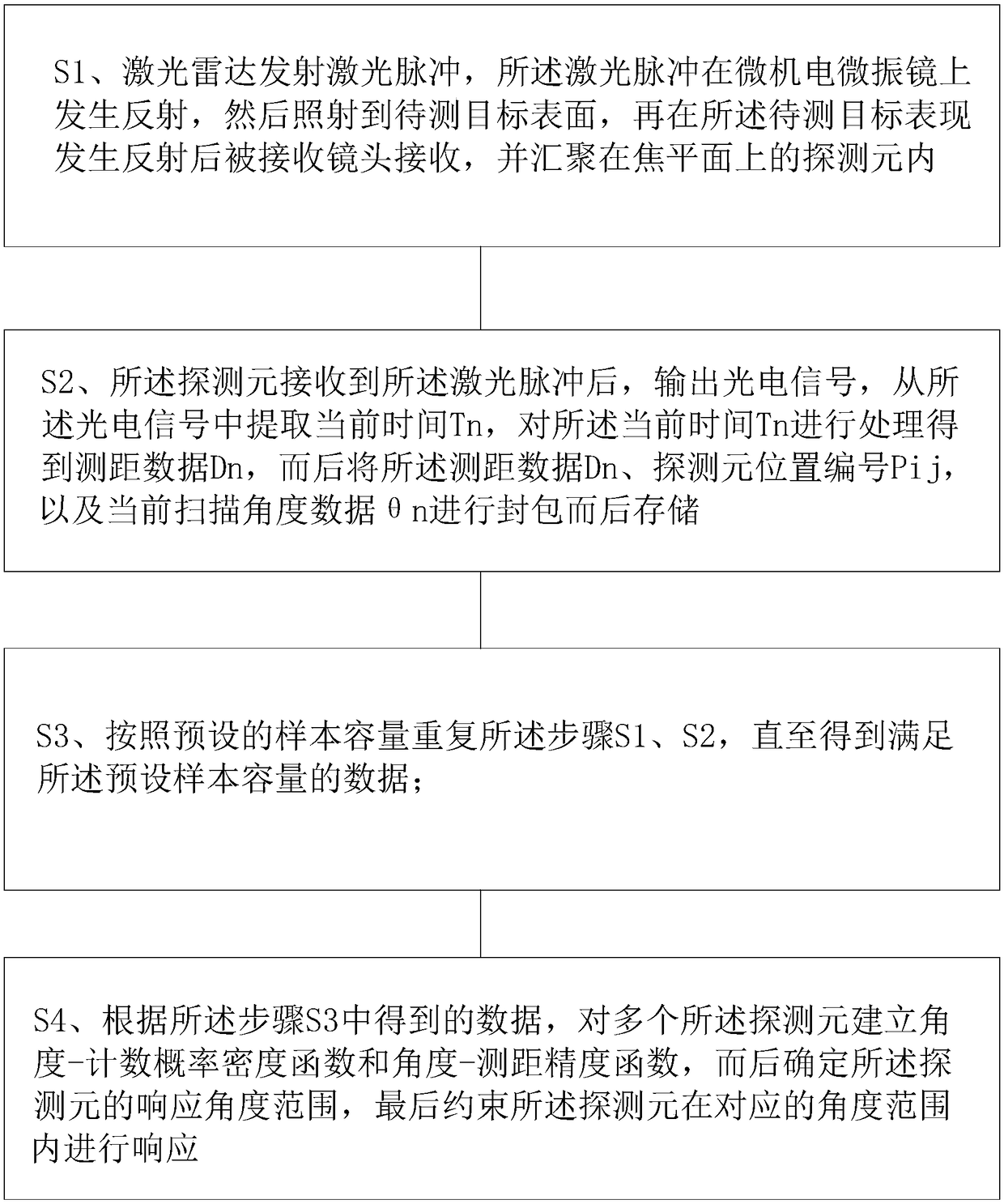
[0023] figure 1 It is a flow chart, showing the laser radar echo processing method based on the optical micro-electro-mechanical system described in one embodiment of the present invention. Such as figure 1 As shown, the laser radar echo processing method based on the optical micro-electromechanical system described in this embodiment of the prese...


PUM


Abstract

The invention proposes a laser radar echo processing method based on an optical MEMS (micro-electro-mechanical system), and the method comprises the steps that a laser radar emits a laser pulse, is reflected on an MEMS micro-galvanometer, is irradiated to the surface of a to-be-tested target, is received by a receiving lens, and is concentrated in a detecting element on a focal plane; S2, the detecting element outputs a photoelectric signal, extracts the current time Tn from the photoelectric signal, obtains the range finding data Dn, and then stores the range finding data Dn, the position number Pij of the detecting element and a current scanning angle data (theta)n for package and storage; S3, the steps S1 and S2 are repeatedly executed according to a preset sample capacity till the datasatisfying the preset sample capacity is obtained; S4, a range of a response angle of the detecting element is determined, and finally the detecting element is constrained to respond within a corresponding angle range. The method does not need an additional high-precision measurement device for assistance, and can achieve the detection, calculation and confirmation of a receiving angle of a lasersignal reflected by the to-be-tested target.

Description

technical field [0001] The invention relates to the technical field of micro-electro-mechanical system scanning, in particular to a laser radar echo processing method based on an optical micro-electro-mechanical system. Background technique [0002] An active detection method based on laser radar in the prior art, its basic working principle is to emit laser light to the target to be detected through the laser radar, and the laser light is irradiated on the target to be detected and reflected on the surface of the target to be detected, and then received by the receiver The laser signal reflected by the target to be measured, the distance between the laser radar and the target to be measured is obtained after measuring the round-trip time of the laser signal. Due to the high coherence, directionality and monochromaticity of laser itself, the active detection method of laser radar can realize the function of long-distance and high-precision ranging, and it is widely used in a...

Claims


Application Information

Patent Timeline
Patent Type & Authority Applications(China)
IPC IPC(8): G01S7/487
CPCG01S7/487
Inventor 陈忻吴小可朱俊
Owner 苏州镭图光电科技有限公司
Why Eureka
Try Eureka