
Sealing device used for brake piston of quick press machine

A sealing device and piston technology, which is applied in fluid pressure actuators, brake actuators, mechanical equipment, etc., can solve the problems of loss of sealing effect and damage of sealing rings, and achieve increased area, stable installation, and optimized flow state Effect

Active Publication Date: 2019-01-01
TIANJIN UNIV
View PDF19 Cites 0 Cited by
  • Summary
  • Abstract
  • Description
  • Claims
  • Application Information

AI Technical Summary

Problems solved by technology

[0007] However, in the preparation process of the fast compressor, that is, during the pressing process of the brake piston, the force direction of the brake piston, that is, the direction of movement, does not coincide with the normal direction of the pressing surface, and the sealing mechanism of the sealing ring relies on Therefore, during the pressing process, there will be a cut-in process between the inclined surface of the brake piston and the inclined surface of the rear cover of the brake cylinder, so that the sealing ring will bear the rolling caused by the interlaced movement of the two inclined surfaces, and then In addition, in the early stage of the compression process of the fast press, there will be high-speed flowing hydraulic oil scouring, which will eventually cause the sealing ring to be easily damaged and lose the sealing effect

Method used


Image

  • Sealing device used for brake piston of quick press machine
  • Sealing device used for brake piston of quick press machine
  • Sealing device used for brake piston of quick press machine

Examples


Embodiment Construction

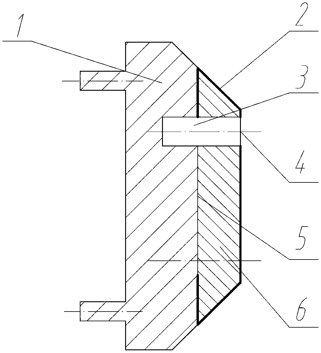
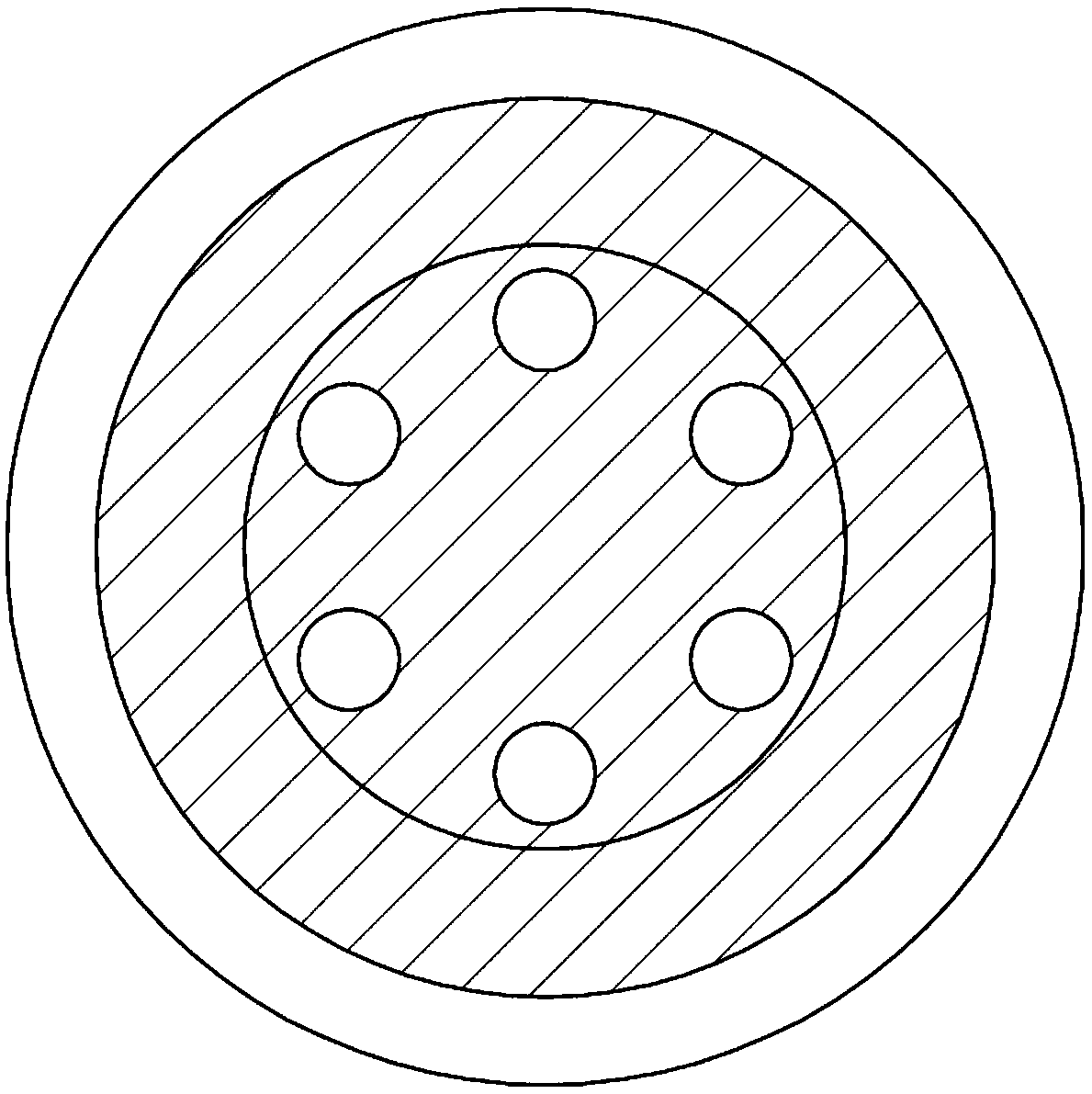
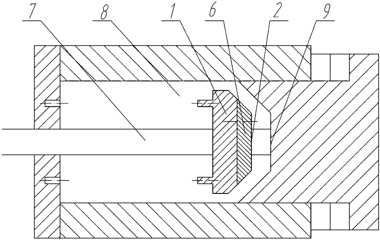
[0023] The disc-shaped brake piston top 6 and the matching disc-groove brake cylinder rear end cover 9 are adopted, and the brake piston top 6 and the brake piston main body 1 are connected by bolts through the reserved bolt holes 3 . Cone type piston top 6 wraps up with the sealing rubber sleeve 2 that size matches with it. The sealing rubber sleeve 2 has a hole at position 3 of the bolt hole on the top of the round table, which is convenient for bolt connection, and an opening at position 5 at the bottom of the round table, which is convenient for the installation of the sealing sleeve.

[0024] Installation method: insert the round table part 6 on the top of the brake piston into the seal sleeve from the opening 5 at the bottom of the seal sleeve, align the bolt holes with the opening 4 of the seal sleeve, and use bolts to connect the top 6 of the brake piston and the main body 1 as a whole , and installed on the connecting rod 7.

[0025] Working process: press the top 6 ...


PUM


Abstract

A sealing device used for a brake piston of a quick press machine comprises a piston top and a brake cylinder rear end cover matched with the piston top, and is characterized in that the piston top isa circular truncated cone type brake piston top; the brake cylinder rear end cover is a circular truncated cone groove type brake cylinder rear cover; the brake piston top and a brake piston body areconnected through a bolt via a reserved bolt hole; the piston top is wrapped with a sealing rubber sleeve matched with the piston top in size; and a hole is reserved in the position, at the bolt holeof the circular truncated cone top, of the sealing rubber sleeve, bolt connection is facilitated, an opening is formed in the bottom of the circular truncated cone, and mounting of the sealing sleeveis facilitated.

Description

Technical field: [0001] The invention relates to a sealing device for a brake piston of a fast press, in particular to an anti-falling sealing device which uses hydraulic oil to establish a pressure environment in a brake cylinder. Background technique: [0002] In the preparation stage of the fast compressor, in order to establish a reverse pressure greater than the air pressure of the driving piston, it is necessary to pump hydraulic oil into the brake cylinder through an oil pump, relying on the incompressibility of the liquid to establish sufficient oil pressure, so that the brake The moving piston is pressed tightly on the rear cover of the brake cylinder, so that the connecting rod between the pistons is in a balanced state, which is convenient for releasing the oil pressure at the beginning of the experiment, so as to achieve the purpose of quickly compressing the gas in the cylinder under the pressure of the piston driven by a large enough air pressure. [0003] In t...

Claims


Application Information

Patent Timeline
IPC IPC(8): F15B15/14F16D65/14F16D121/04
CPCF15B15/1423F15B15/1447F15B15/1452F16D65/14F16D2121/04
Inventor 潘家营张泽卫海桥舒歌群刘昌文胡祯
Owner TIANJIN UNIV
Learn More