
Calibration method and system for three-dimensional imaging system based on rotating shaft and binocular camera

A binocular camera and three-dimensional imaging technology, applied in image analysis, image data processing, instruments, etc., can solve the problems of large error in calibration results, error accumulation, large error, etc., and achieve the effect of improving accuracy and avoiding error accumulation

Active Publication Date: 2019-01-01
SHENZHEN ESUN DISPLAY
View PDF3 Cites 29 Cited by
  • Summary
  • Abstract
  • Description
  • Claims
  • Application Information

AI Technical Summary

Problems solved by technology

That is to say, the binocular system is calibrated first, and then the rotation axis is calibrated based on the results of the binocular system calibration, which will lead to errors in the parameters during the two optimization iterations during the entire calibration process. Accumulation, in the case of errors, may lead to large errors in the final calibration results
[0005] To sum up, among the related technical solutions, the related technical solution of the camera calibration of the rotation axis of the binocular system has the problem of excessive errors caused by the accumulation of errors, which leads to the accuracy of the calibration of the 3D imaging system based on the rotation axis and the binocular camera. Insufficient rate

Method used


Image

  • Calibration method and system for three-dimensional imaging system based on rotating shaft and binocular camera
  • Calibration method and system for three-dimensional imaging system based on rotating shaft and binocular camera
  • Calibration method and system for three-dimensional imaging system based on rotating shaft and binocular camera

Examples


Embodiment Construction

[0055] The technical solutions in the embodiments of the present invention will be clearly and completely described below in conjunction with the accompanying drawings in the embodiments of the present invention. Obviously, the described embodiments are only some of the embodiments of the present invention, not all of them. Based on the embodiments of the present invention, all other embodiments obtained by persons of ordinary skill in the art without making creative efforts all belong to the protection scope of the present invention.

[0056] As mentioned earlier, in order to solve the above-mentioned related technical solutions for the camera calibration of the binocular system and the rotation axis, there is an excessive error caused by the accumulation of errors, which leads to insufficient accuracy of the 3D imaging system calibration based on the rotation axis and the binocular camera. To solve the technical problem, in the present invention, a method for calibrating a th...


PUM


Abstract

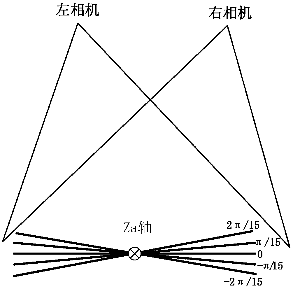
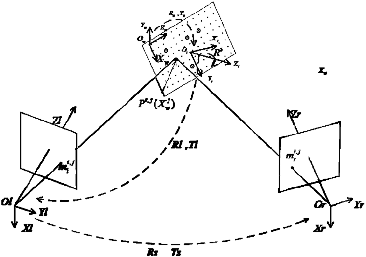
The embodiment of the invention discloses a calibration method of a three-dimensional imaging system based on a rotating shaft and a binocular camera. The method is based on a three-dimensional imaging system comprising a rotating platform and a binocular camera. A target with at least one mark point is fixed on the rotating platform. The binocular camera comprises a first camera and a second camera; the method comprises the following steps: acquiring first and second images through the first and second cameras under at least two preset rotation angles, and acquiring pixel coordinates of marker points in the first and second images; according to the world coordinates of the landmark points in the world coordinate system and the first, the pixel coordinates of the marker points in the second image are calibrated and the calibration parameters are obtained. The calibration parameters include the rotational parameters, the equipment internal parameters corresponding to the first camera and the second camera, the equipment external parameters, and the pixel coordinate transformation relationship between the first and second cameras. By adopting the invention, the calibration accuracy of the three-dimensional imaging system based on the rotating shaft and the binocular camera can be improved.

Description

technical field [0001] The present invention relates to the technical field of machine vision, in particular to a calibration method and system for a three-dimensional imaging system based on a rotating shaft and a binocular camera. Background technique [0002] Camera calibration is a very important technology in image processing technology. In the process of image measurement and machine vision applications, in order to determine the relationship between the three-dimensional geometric position of a point on the surface of a space object and its corresponding point in the image, it is necessary to establish the camera imaging Geometric model, these geometric model parameters are camera parameters. Under most conditions, these parameters must be obtained through experiments and calculations, and the process of solving the parameters is called camera calibration. [0003] The measurement technology based on the binocular 3D camera is an important part of the computer 3D det...

Claims


Application Information

Patent Timeline
IPC IPC(8): G06T7/80
CPCG06T7/85
Inventor 何懂喻晓李尚贵陈海龙刘梦龙
Owner SHENZHEN ESUN DISPLAY
Learn More