A method of manufacturing a fully insulated lightning arrester

A manufacturing method and lightning arrester technology, which are applied in the direction of adding resistors at the lead-out end and manufacturing encapsulation/shell resistors, etc., can solve problems such as eccentricity of the arrester core group, partial discharge, and uneven thickness of the rubber coating, and achieve uniform rubber coating Effect

Active Publication Date: 2020-06-23
NANYANG ZHONGXIANG POWER ELECTRONICS +1
View PDF4 Cites 0 Cited by
  • Summary
  • Abstract
  • Description
  • Claims
  • Application Information

AI Technical Summary

Problems solved by technology

[0004] In order to overcome the above-mentioned shortcomings of the prior art, the invention proposes a manufacturing method for a fully insulated arrester, which adopts specially made tooling for molding, which not only solves the problem of loose connection between the lead wire and the core group during the manufacture of the arrester and the generation of partial discharge. , and solve the problem of eccentric arrester core group and uneven thickness of rubber covering in the production process

Method used


Image

  • A method of manufacturing a fully insulated lightning arrester

Examples


Embodiment 1

[0018] Embodiment 1: A method for making a fully insulated arrester, suitable for a 10 KV arrester, comprising the following steps:

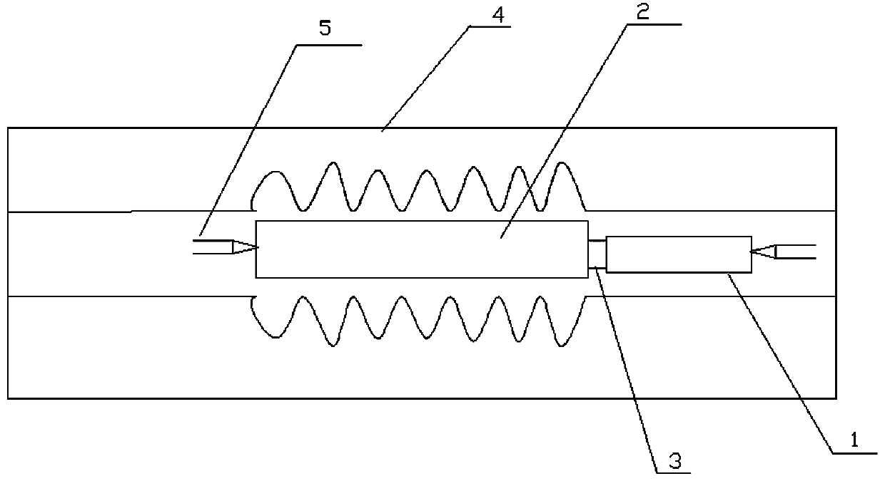
[0019] (1) Use the tooling 1 to replace the insulated lead wire and screw it into the terminal 3 at the end of the wound core group 2, and tighten the connection between the tooling 1 and the terminal 3;

[0020] (2) Put the core group 2 and the tooling 1 into the mold 4 filled with silicone rubber melt, so that the silicone rubber completely covers the core group 2 and the connection between the core group 2 and the tooling 1, and the mold 4 is provided on both sides There is a center positioning device, and the center positioning device is composed of a pair of compression bolts 5 and a positioning frame with internal threads that are matched with the compression bolts. The compression bolts 5 pass through the positioning frame to withstand the core group 2 and the tooling 1 to fix the position of the core group 2 in the mold 4. During the mol...

Embodiment 2

[0023] Embodiment 2: A method for making a fully insulated lightning arrester, suitable for 24 KV lightning arresters, comprising the following steps:

[0024] (1) Use the tooling 1 to replace the insulated lead wire and screw it into the terminal 3 at the end of the wound core group 2, and tighten the connection between the tooling 1 and the terminal 3;

[0025] (2) Put the core group 2 and the tooling 1 into the mold 4 filled with silicone rubber melt, so that the silicone rubber completely covers the core group 2 and the connection between the core group 2 and the tooling 1, and the mold 4 is provided on both sides There is a center positioning device. The center positioning device is composed of a pair of compression bolts 5 and a positioning frame with internal threads that are matched with the compression bolts. end, so that the position of the core group 2 in the mold 4 is fixed, and the core group will not be deviated due to the huge pressure of the machine during the ...


PUM


Abstract

A manufacture method of a fully insulated lightning arrester includes such steps as adopting a special tool to replace an insulated lead to be screwed into a terminal of a core group end part for mould pressing , solving the problem that an insulated lead and core group crimping part is desoldered, generating partial discharge, and causing reduction of the percent of pass. At the same time, the tool has the function of positioning, so that the position in the core group mold is fixed, during the mould pressing process, the core group does not deviate due to the tremendous pressure of the machine, so that the glue around the core group is uniform, there will be no thick side and thin side, after compression molding, the tool is screwed out, a small section of an insulation layer at one endof the insulated lead is peeled off, is plugged into one end of a specially made hollow stud for crimping, after crimping into one body, a sealing adhesive is smeared at the joint, the terminal of thelightning arrester is screwed in, and after assembly is finished, the lightning arrester is placed still, and the adhesive solidifies.

Description

technical field [0001] The invention belongs to the technical field of arrester manufacture, and in particular relates to a method for manufacturing a fully insulated arrester. Background technique [0002] With the development of power systems, the requirements for surge arresters are also getting higher and higher. Fully insulated surge arresters are metal oxide surge arresters used to protect electrical equipment from overvoltage damage. They have reasonable structure, small size, light weight, and explosion-proof performance. Good, not limited by the insulation distance between phase wires, flexible installation, convenient wiring, etc., widely used in the insulation between phase wire and phase wire and between phase wire and ground of important electrical equipment such as rotating motors, parallel compensation capacitor banks, and transformers Damaged by overvoltage, it can also be used for overvoltage insulation protection of various electrical equipment in compact s...

Claims


Application Information

Patent Timeline
Patent Type & Authority Patents(China)
IPC IPC(8): H01C17/02H01C17/28
CPCH01C17/02H01C17/28
Inventor 康定增李秀坤陈成刚铁九峰陈展
Owner NANYANG ZHONGXIANG POWER ELECTRONICS
Why Eureka
Try Eureka