Current collector structure, battery structure and preparation method of current collector structure

A current collector and current collector technology, applied in secondary batteries, structural parts, battery pack parts, etc., can solve the problems of inability to carry large currents, wire welding, thick current collector legs, etc., to achieve simple structure, adaptable thickness, The effect of convenient welding

Pending Publication Date: 2019-01-01
SHENZHEN KEDALI IND CO LTD
View PDF6 Cites 0 Cited by
  • Summary
  • Abstract
  • Description
  • Claims
  • Application Information

AI Technical Summary

Problems solved by technology

[0005] One of the objectives of the present invention is to provide a current collector structure and a battery structure to solve the current collector leg that is too thick to be welded with the wire smoothly and too thin to carry the load caused by the current collector being a straight plate with the same thickness in the prior art. Technical problems with high current

Method used


Image

  • Current collector structure, battery structure and preparation method of current collector structure
  • Current collector structure, battery structure and preparation method of current collector structure
  • Current collector structure, battery structure and preparation method of current collector structure

Examples


Embodiment Construction

[0031] In order to make the technical problems solved by the present invention, the technical solutions adopted and the technical effects achieved clearer, the technical solutions of the embodiments of the present invention will be further described in detail below in conjunction with the accompanying drawings. Obviously, the described embodiments are only the technical solutions of the present invention. Some, but not all, embodiments. Based on the embodiments of the present invention, all other embodiments obtained by those skilled in the art without making creative efforts belong to the protection scope of the present invention.

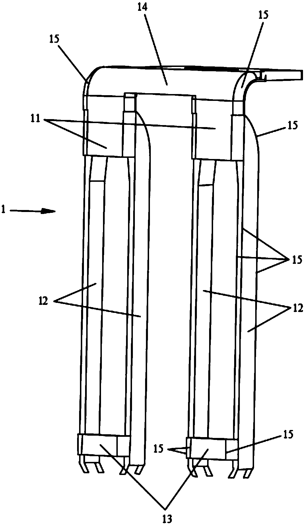
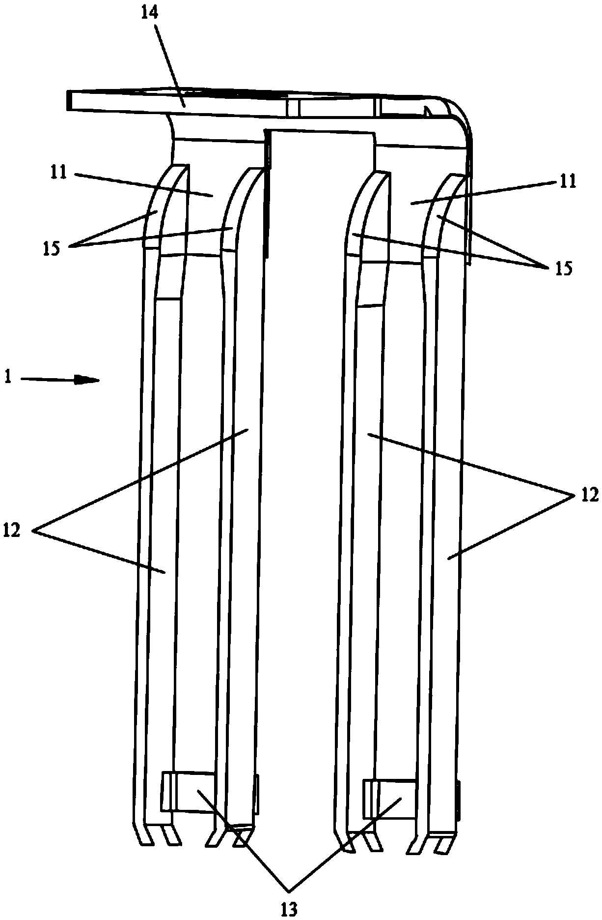
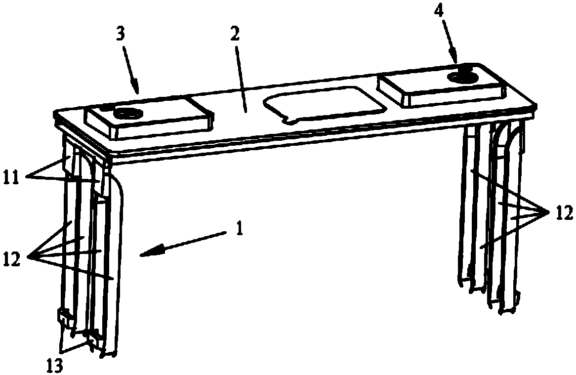
[0032] Such as figure 1 and figure 2 As shown, this embodiment provides a current collector structure 1, including a collector body 11 and a collector leg 12, one end of the collector body 11 is connected to the cover plate 2, and the other end is connected to a plurality of collector legs 12, and the collector The fluid body 11 and the collect...


PUM

PropertyMeasurementUnit
Thicknessaaaaaaaaaa
Thicknessaaaaaaaaaa

Abstract

The invention discloses a current collector structure, a battery structure and a preparation method of the current collector structure, belonging to the technical field of batteries. The current collector structure comprises a current collector body and current collector legs, wherein one end of the current collector body is connected with a cover plate and the other end is connected with the plurality of current collector legs, and the current collector body and the current collector legs are staggered, so that the current collector body and the current collector legs can be arranged in different thicknesses; the thickness range of the collector body is 1.7 mm-1.9 mm, and the thickness range of the collecting legs is 0.9 mm-1.1 mm, thus the thickness of the current collector body is larger, the relatively large current can be borne, and the thickness of the current collector legs is smaller, so that welding with wires is facilitated. The battery structure provided by the invention comprises a cover plate and the abovementioned current collector structure, wherein the cover plate structure comprises a cover plate, and the current collector legs are respectively welded with wires. The invention has the advantages of simple structure, adapting the thickness to the requirements of various parts, convenient welding with the wires, and being capable of bearing relatively large current.

Description

technical field [0001] The invention relates to the technical field of batteries, in particular to a current collector structure, a battery structure and a method for preparing the current collector structure. Background technique [0002] A battery usually includes a cover structure and a current collector structure, wherein, [0003] Current collector, as the name implies, refers to the structure or parts that collect current. In lithium-ion batteries, it mainly refers to metal foil, such as copper foil and aluminum foil. The general term can also include polar ears. Its function is mainly to gather the current generated by the active materials of the battery to form a larger current output. [0004] When assembling into the battery, the current collecting leg needs to be connected with the cell through a wire. When the wire is welded to the current collecting leg, the thickness of the current collecting leg should not be too large, otherwise it is not conducive to ultra...

Claims


Application Information

Patent Timeline
IPC IPC(8): H01M2/26H01M4/72H01M10/0525H01M4/70H01M50/531
CPCH01M4/70H01M4/72H01M10/0525H01M50/531Y02E60/10
Inventor 励建炬范洪斌
Owner SHENZHEN KEDALI IND CO LTD
Why Eureka
Try Eureka