Coding circuit

An encoding circuit and encoding technology, applied in the field of encoding circuits, can solve the problems of high cost, single function, complex encoding circuit structure, etc., and achieve the effect of fewer electronic components, low cost, and simple circuit structure

Inactive Publication Date: 2019-01-01
杨桂凤
View PDF0 Cites 0 Cited by
  • Summary
  • Abstract
  • Description
  • Claims
  • Application Information

AI Technical Summary

Problems solved by technology

[0002] In the prior art, most of the encoding circuits have complex structures, many electronic components used, single functions, and high cost

Method used


Image

  • Coding circuit

Examples


Embodiment Construction

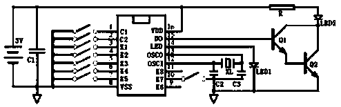
[0007] Such as figure 1 As shown, an encoding circuit includes: power supply, first capacitor C1, encoding chip, second capacitor C2, third capacitor C3, first diode LED1, second diode LED2, resistor R, first three Transistor Q1, second triode Q2 and crystal oscillator XL; pins 1, 2, 3, 4, 5, 6, 7 and 10 of the coding chip are connected to their respective control switches, and one end of the first capacitor C1 is connected to the coding chip 8 pins, the other end is connected to the 16 pins of the encoding chip, the power supply is connected in parallel to both ends of the first capacitor C1; the base of the first triode Q1 is connected to the 15 pins of the encoding chip, and the collector of the first triode Q1 Connect the second diode LED2 and resistor R in sequence to pin 16 of the encoding chip, the emitter of the first transistor Q1 is connected to the base of the second transistor Q2, and the collector of the second transistor Q2 Connect the collector of the first tri...


PUM


Abstract

The invention discloses a coding circuit. The circuit includes a power supply, a first capacitor C1, a coding chip, a second capacitor C2, a third capacitor C3, a first diode LED 1, a second diode LED2, a resistor R, a first triode Q1, a second triode Q2 and a crystal oscillator XL. The beneficial effects of the circuit are that the circuit is simple in structure and low in cost, and electronic components to be used are less.

Description

technical field [0001] The invention relates to the technical field of circuits, in particular to an encoding circuit. Background technique [0002] In the prior art, most of the encoding circuits have complex structures, many electronic components used, single functions, and high cost. Contents of the invention [0003] The technical problem to be solved by the present invention is to provide an encoding circuit with simple circuit structure, low cost and less electronic components. [0004] In order to solve the above technical problems, the present invention provides an encoding circuit, including: a power supply, a first capacitor C1, an encoding chip, a second capacitor C2, a third capacitor C3, a first diode LED1, a second diode LED2, Resistor R, first triode Q1, second triode Q2 and crystal oscillator XL; pins 1, 2, 3, 4, 5, 6, 7 and 10 of the encoding chip are respectively connected to their respective control switches, and the first capacitor One end of C1 is co...

Claims


Application Information

Patent Timeline
Patent Type & Authority Applications(China)
IPC IPC(8): H03K19/082
CPCH03K19/082
Inventor 杨桂凤
Owner 杨桂凤
Why Eureka
Try Eureka