Heat radiation structure for plate body, and manufacturing method thereof
A technology of a heat dissipation structure and a manufacturing method, which is applied in the field of thermal management, can solve the problem of low thermal efficiency of the heat dissipation structure of a plate body, and achieve the effect of improving the efficiency
- Summary
- Abstract
- Description
- Claims
- Application Information
AI Technical Summary
Problems solved by technology
Method used
Image

Examples
Embodiment 1
[0030] An embodiment of the present invention provides a board body heat dissipation structure, and the board body heat dissipation structure is attached to the surface of the board body or embedded in the inside of the board body. The board body heat dissipation structure can be used to dissipate heat for high-power devices such as power devices or laser devices arranged on the PCB, and of course it can also be used to dissipate heat for other boards.
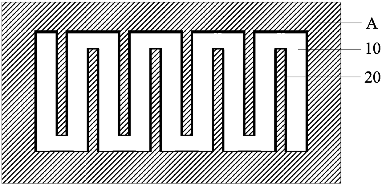
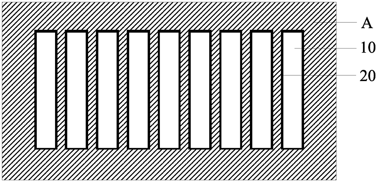
[0031] Figure 2E Shows a longitudinal sectional view of a plate body heat dissipation structure according to an embodiment of the present invention, Figure 1A and Figure 1B for Figure 2E Two possible top views of the heat dissipation structure of the plate in the longitudinal sectional view obtained by cross-cutting along XX'. Such as Figure 1A , Figure 1B and Figure 2E As shown, the board heat dissipation structure includes a core board A and at least one cover board B.
[0032] A groove 10 is provided on at least...
Embodiment 2
[0039] image 3 A flow chart of a manufacturing method of a plate heat dissipation structure according to an embodiment of the present invention is shown. This method can be used to manufacture the plate heat dissipation structure described in the first embodiment. Such as image 3 As shown, the method includes the following steps:
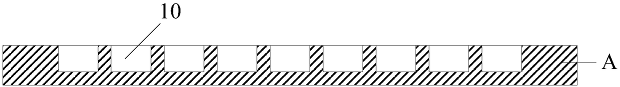
[0040] S101: Provide a groove on at least one surface of the core board, and the groove forms at least one continuous channel on the surface of the core board. Such as Figure 2A Shown, where A is the core plate, 10 is the groove.
[0041] S102: Forming a first metal layer on the surface of the core board on which grooves are opened. The first metal layer covers the inner wall of the groove. Such as Figure 2B As shown, 20 is the first metal layer.
[0042] S103: Form a second metal layer on at least one surface of the cover plate. Such as Figure 2CAs shown, where B is the cover plate, and 40 is the second metal layer.
[0043] S104: B...
Embodiment 3
[0047] The embodiment of the present invention provides another plate heat dissipation structure, which is attached to the surface of the plate or embedded in the inside of the plate. The board heat dissipation structure can be used to dissipate heat for high power consumption devices such as power devices or laser devices arranged on the PCB, and of course it can also be used to dissipate heat for other boards.
[0048] Figure 4F Shows a longitudinal sectional view of a plate body heat dissipation structure according to an embodiment of the present invention, Figure 1A , Figure 1B for Figure 4F Two possible top views of the heat dissipation structure of the plate in the longitudinal sectional view obtained by cross-cutting along XX'. Such as Figure 1A , Figure 1B and Figure 4F As shown, the board heat dissipation structure includes a core board A, a first cover board B1 and a second cover board B2.
[0049] The core plate A is provided with a through hole 10 passi...
PUM
 Abstract
Description
Claims
Application Information
 - R&D
- Intellectual Property
- Life Sciences
- Materials
- Tech Scout
- Unparalleled Data Quality
- Higher Quality Content
- 60% Fewer Hallucinations
Browse by: Latest US Patents, China's latest patents, Technical Efficacy Thesaurus, Application Domain, Technology Topic, Popular Technical Reports.
© 2025 PatSnap. All rights reserved.Legal|Privacy policy|Modern Slavery Act Transparency Statement|Sitemap|About US| Contact US: help@patsnap.com