Temperature-controlled and safe catalytic oxidation VOCs treatment reactor

A catalytic reactor and catalytic oxidation technology, used in chemical instruments and methods, gas treatment, membrane technology, etc., can solve the problems of increasing equipment manufacturing costs, large thermal stress on equipment, fast heat dissipation time, etc., and achieve accurate temperature of thermally conductive materials. Controllable, significant energy-saving effect, and the effect of reducing electricity load

Pending Publication Date: 2019-01-04
CHINA PETROLEUM & CHEM CORP +1
View PDF0 Cites 0 Cited by
  • Summary
  • Abstract
  • Description
  • Claims
  • Application Information

AI Technical Summary

Problems solved by technology

The initial reaction preparation time is long, inefficient, and has the following disadvantages:
[0004] 1) The temperature change in the reactor is closely related to the VOCs material concentration. The higher the VOCs material concentration, the greater the heat released by the reactor itself, and the lack of necessary temperature adjustment means
[0005] 2) The reactor itself lacks effective heat storage capacity, and the heat released by the reactor itself cannot be effectively stored; conventional reactors have weak heat storage capacity, and the reactor is usually filled with heat storage ceramics for heat storage, and heat storage ceramics are usually only There is a heat storage capacity, the heat storage time is long, and the heat dissipation time is fast, which cannot effectively meet the demand
[0006] 3) Due to the lack of necessary temperature adjustment measures in the traditional reactor, the design temperature of the reactor is relatively high, and the equipment is subjected to large thermal stress, which increases the production cost of the equipment

Method used


Image

  • Temperature-controlled and safe catalytic oxidation VOCs treatment reactor
  • Temperature-controlled and safe catalytic oxidation VOCs treatment reactor
  • Temperature-controlled and safe catalytic oxidation VOCs treatment reactor

Examples


Embodiment Construction

[0025] The following will clearly and completely describe the technical solutions in the embodiments of the present invention with reference to the drawings in the embodiments of the present invention.

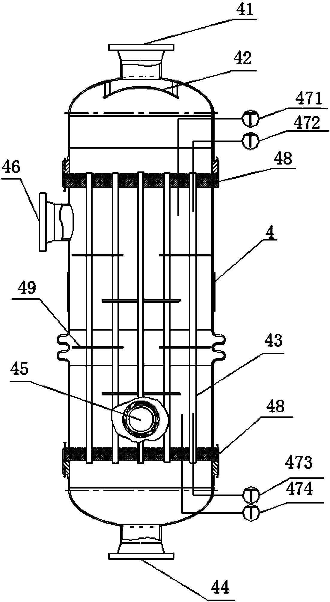
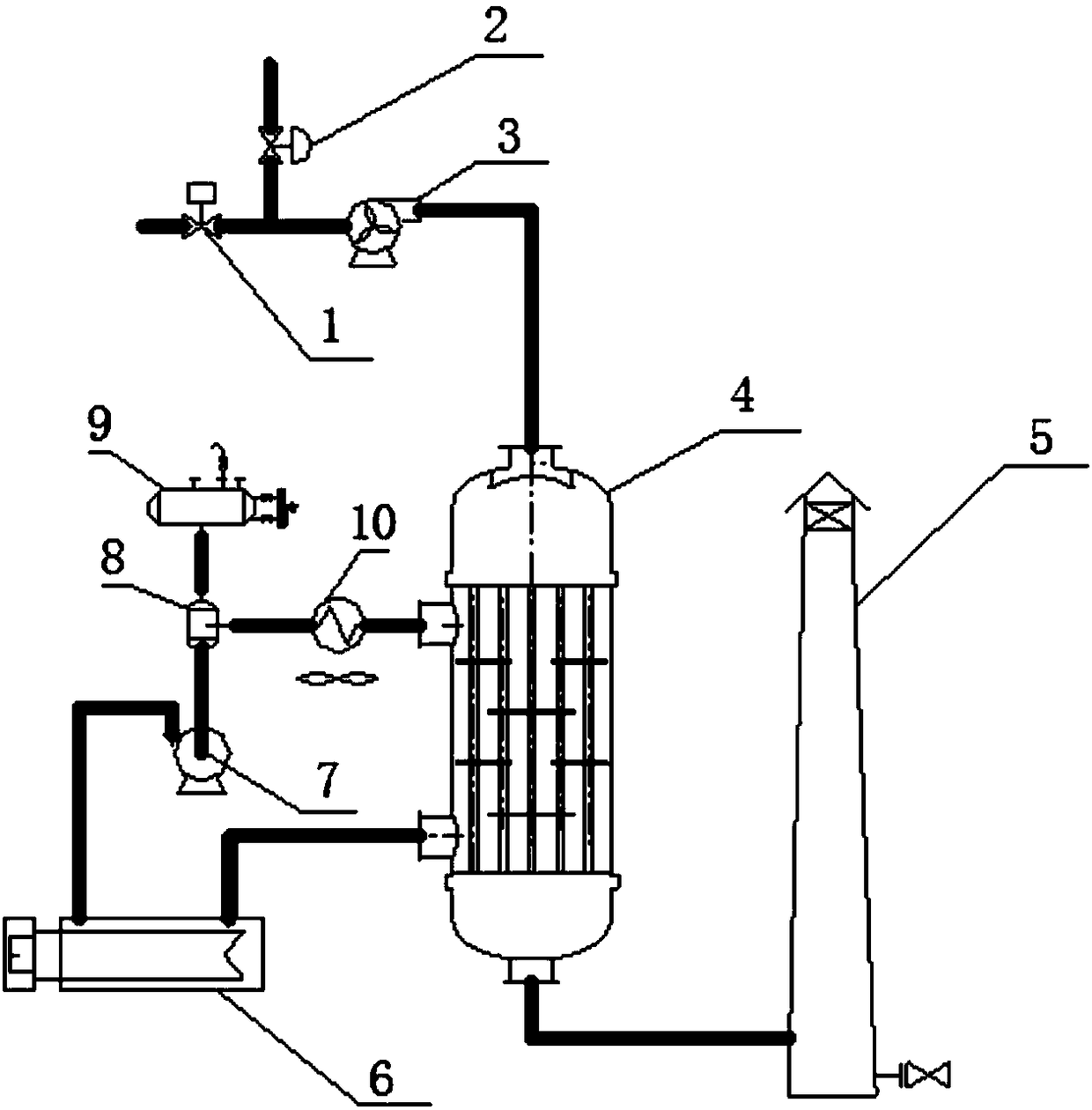
[0026] The invention provides a temperature-controlled safe catalytic oxidation VOCs treatment reactor, such as figure 1 With the structure shown in the catalytic reactor, the heat storage capacity of the catalytic reactor is significantly improved without reducing the heat exchange efficiency, and the heat transfer oil can be heated in advance to store heat energy. Especially in the case of large flow rate changes or intermittent air intake, it can meet the requirements of the working conditions by adjusting the heat exchange oil flow rate; thereby reducing system preparation time, improving device operation and VOCs processing efficiency; and is especially suitable for processing The situation of intermittent material intake and large flow VOCs intake.

[0027] Such as fig...


PUM


Abstract

The invention discloses a temperature-controlled and safe catalytic oxidation VOCs treatment reactor. The reactor comprises a catalytic reactor, a gas inlet is formed in the top of the catalytic reactor, a gas outlet is formed in the bottom, reactor tubes are arranged longitudinally in the catalytic reactor, the upper and lower ends of the reactor tubes are fixed to a baffle plate and protrude from the baffle plate, sealed cavities are formed between the catalytic reactor, the reactor tubes and the baffle plate, and the sealed cavities are filled with recyclable heat transfer oil; a heat transfer oil outlet is formed in the upper portion of the catalytic reactor, and a heat transfer oil inlet is formed in the lower portion; the upper layers of the insides of the reactor tubes are filled with stainless steel wire meshes or porcelain balls, the middle layers are filled with a catalyst, and the lower layers are filled with heat conduction and supporting porcelain balls. The reactor has strong heat storage capacity, precise and controllable reaction temperature and safety and reliability, and is particularly suitable for handling large-flow and intermittent material air inlet.

Description

technical field [0001] The invention relates to the field of volatile organic compounds (VOCs) treatment, in particular to a treatment reactor with strong heat storage capacity, precise and controllable reaction temperature, safe, reliable and efficient treatment of VOCs tail gas. Background technique [0002] Catalytic oxidation VOCs treatment technology is usually used to treat low-concentration VOCs materials. In recent years, with the upgrading of national and local environmental protection standards, VOCs emission limits have become increasingly stringent. Traditional VOCs treatment technologies such as adsorption and condensation methods cannot treat low-concentration VOCs materials with high efficiency for a long time, and this low-concentration VOCs materials are usually destroyed by catalytic oxidation VOCs treatment terminal technology, so as to meet the requirements of environmental protection indicators. [0003] In the existing low-temperature catalytic oxidatio...

Claims


Application Information

Patent Timeline
Patent Type & Authority Applications(China)
IPC IPC(8): B01D53/88B01D53/44
CPCB01D53/8687B01D53/88B01D2255/10B01D2255/70B01D2257/708
Inventor 尹树孟张健中于辉牟小冬程龙军
Owner CHINA PETROLEUM & CHEM CORP
Why Eureka
Try Eureka