Grinding device of pipelines for building construction

A technology of grinding device and building construction, applied in the direction of grinding drive device, grinding machine, manufacturing tools, etc., can solve the problems of unpolished, unfavorable for workers' grinding work, and high operating intensity of workers, so as to reduce work intensity, improve grinding efficiency and Polishing quality and reducing the effect of manual operation

Active Publication Date: 2019-01-04
江苏复华光电科技有限公司
View PDF8 Cites 16 Cited by
  • Summary
  • Abstract
  • Description
  • Claims
  • Application Information

AI Technical Summary

Problems solved by technology

However, most of the grinding of the surface of the existing pipelines is carried out by using a grinding machine. Although the use of a grinding machine can grind away the barbs and sundries on the surface of the pipe fittings, for more and more stringent construction and production, the grinding machine polishing will obviously lead to The smoothness of the surface of the pipe is inconsistent, which affects the appearance of the pipe, which is not conducive to the subsequent painting and anti-rust, which will lead to premature rusting of the pipe and affect the normal use of the pipe; and the existing grinding machine is difficult to adjust and control, and it all depends on the operator. Grinding by experience, the quality of the grinding varies; in addition, the hand-held grinder produces a lot of dust during the grinding process, which affects the health of the operator
For pipes with larger diameters, it is more difficult to turn over the pipes, and it is not conducive to workers to perform grinding work. During the grinding process, workers have high operating intensity and are prone to unpolished situations.

Method used


Image

  • Grinding device of pipelines for building construction
  • Grinding device of pipelines for building construction
  • Grinding device of pipelines for building construction

Examples


specific Embodiment approach 1

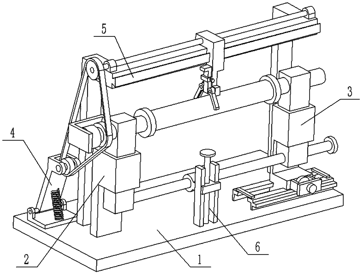
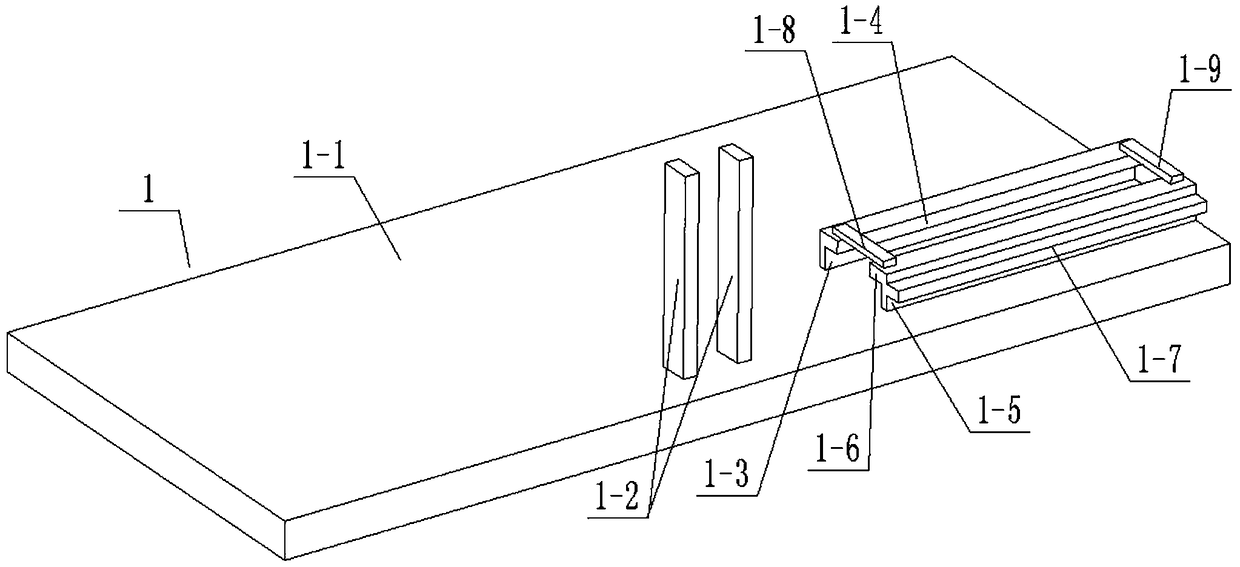
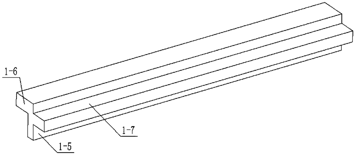
[0029] Combine below Figure 1-11 Describe this embodiment, a pipeline grinding device for construction, including a base 1, a left support base 2, a right support base 3, a tensioning wheel 4, a support frame 5 and an adjustment rod 6, and the base 1 includes a bottom plate 1- 1. Guide rod 1-2, first limit plate 1-3, first convex edge 1-4, second limit plate 1-5 and second convex edge 1-6; two guide rods 1-2 are opposite Fixedly connected on the base plate 1-1, the first limiting plate 1-3 and the second limiting plate 1-5 are fixedly connected to one end of the base plate 1-1, the first limiting plate 1-3 and the second limiting plate The inner sides of 1-5 are respectively fixedly connected with a first protruding edge 1-4 and a second protruding edge 1-6;

[0030]The left support seat 2 includes a left support plate 2-1, a left sliding sleeve 2-2, a left height adjustment seat 2-3, a left rotating shaft 2-4, a left top plate 2-5, a left convex circle 2-6, Motor I 2-7 and...

specific Embodiment approach 2

[0034] Combine below Figure 1-11 To illustrate this embodiment, the tensioning pulley 4 includes a support seat 4-1, a rotating shaft 4-2, a shaft seat plate 4-3, a shaft fixing seat 4-4, a short shaft 4-5, and a tensioning pulley 4- 6 and tension spring 4-7; Support seat 4-1 is fixedly connected on the base plate 1-1, and the two ends of rotating shaft 4-2 are respectively connected to the two ends of support seat 4-1 through belt seat bearing rotation, and rotating shaft 4- 2 Rotate around its own axis and have axial positioning, one end of the shaft seat plate 4-3 is fixedly connected to the rotating shaft 4-2, the other end of the shaft seat plate 4-3 is fixedly connected to the shaft fixing seat 4-4, the short shaft 4 -5 is rotatably connected to the shaft fixing seat 4-4 through a bearing with seat, and the tension pulley 4-6 is fixedly connected to the short shaft 4-5, and the short shaft 4-5 and the tension pulley 4-6 revolve around their own axis Rotate and have axi...

specific Embodiment approach 3

[0035] Combine below Figure 1-11 To illustrate this embodiment, the base 1 further includes a rack I1-7; the outer surface of the second limiting plate 1-5 is fixedly connected with the rack I1-7.

[0036] The right support base 3 also includes a motor II 3-9 and a gear 3-10; the motor II 3-9 is fixedly connected to the sliding base 3-7 through the motor base, and the gear 3-10 is fixedly connected to the output shaft of the motor II 3-9 Above, the gear 3-10 rotates around its own axis and has axial positioning, the gear 3-10 is meshed with the rack Ⅰ1-7 for transmission, and the motor Ⅱ3-9 is a forward and reverse motor, and the motor Ⅱ3-9 is connected to the power supply and control through wires The switch is turned on, the motor II 3-9 drives the gear 3-10 to rotate, and when the gear 3-10 rotates, the sliding base 3-7 is driven to move left and right by meshing with the rack I 1-7.


PUM


Abstract

The invention relates to the technical field of pipeline processing, in particular to a grinding device of pipelines for building construction. Two guide rods are fixedly connected to a baseboard. A first limiting board and a second limiting board are fixedly connected to one end of the baseboard. The inner side faces of the first limiting board and the second limiting board are both fixedly connected with a first convex edge and a second convex edge. One end of a left supporting board is fixedly connected to the baseboard, and the other end of the left supporting board is fixedly connected with a left sliding sleeve. The middle end of a left height adjustment seat is slidably connected into the left sliding sleeve. According to the grinding device of the pipelines for building construction, the pipelines can be driven to rotate in operation, and convenient turnover of the pipelines is achieved. All-round grinding of the pipelines is realized by reciprocating motion of a grinding board, the grinding efficiency and the grinding quality of the pipelines are improved, manual operation is reduced, and the working intensity of workers is reduced. The grinding device of the pipelines canbe suitable for grinding of the pipelines with different pipe diameters, and meanwhile the grinding speed can further be adjusted by adjusting the pressure between the pipelines and the grinding board.

Description

technical field [0001] The invention relates to the technical field of pipeline processing, in particular to a pipeline grinding device for building construction. Background technique [0002] In the process of building construction, various types of steel pipes or pipes are often used. Before the pipes are welded and installed, the pipes often need to be polished to facilitate the smooth development of subsequent installation, welding and anti-rust processes. However, most of the grinding of the surface of the existing pipelines is carried out by using a grinding machine. Although the use of a grinding machine can grind away the barbs and sundries on the surface of the pipe fittings, for more and more stringent construction and production, the grinding machine polishing will obviously lead to The smoothness of the surface of the pipe is inconsistent, which affects the appearance of the pipe, which is not conducive to the subsequent painting and anti-rust, which will lead to...

Claims


Application Information

Patent Timeline
Patent Type & Authority Applications(China)
IPC IPC(8): B24B5/04B24B41/06B24B47/12B24B47/16B24B41/02
CPCB24B5/04B24B41/02B24B41/062B24B47/12B24B47/16
Inventor 何双菊
Owner 江苏复华光电科技有限公司
Why Eureka
Try Eureka