A rotary aircraft based on a new type of flap rudder surface

A flapped rudder, rotating body technology, which is applied in the directions of aerospace aircraft, aircraft, and landing devices for aerospace vehicles, can solve problems such as adverse effects on rudder safety and effectiveness, limiting weapon damage power, and difficulty in loading internal mechanisms. , to avoid mutual interference between body and wings, eliminate aerodynamic interference and aerodynamic heating problems, and improve the effective strike distance and strike range.

Pending Publication Date: 2019-01-04
CHINA ACAD OF AEROSPACE AERODYNAMICS
View PDF0 Cites 4 Cited by
  • Summary
  • Abstract
  • Description
  • Claims
  • Application Information

AI Technical Summary

Problems solved by technology

Although the thermal protection pressure of the trailing edge rudder surface is small, the rudder shaft will still have obvious thermal load problems at high angles of attack, which will adversely affect the safety and effectiveness of the rudder
In addition, under the premise of a given outer envelope, the four tail fins of the rotatable aircraft will greatly reduce the actual space of the fuselage, which will bring difficulties to the loading of the internal mechanism, and also reduce the amount of charge, which limits the weapon's capacity. Damage power

Method used


Image

  • A rotary aircraft based on a new type of flap rudder surface
  • A rotary aircraft based on a new type of flap rudder surface
  • A rotary aircraft based on a new type of flap rudder surface

Examples


Embodiment Construction

[0027] The present invention will be described in detail below in conjunction with the accompanying drawings and specific embodiments.

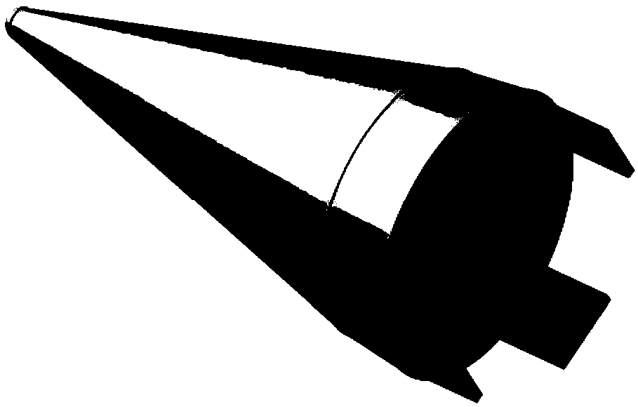
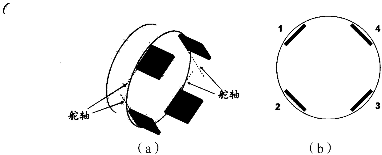
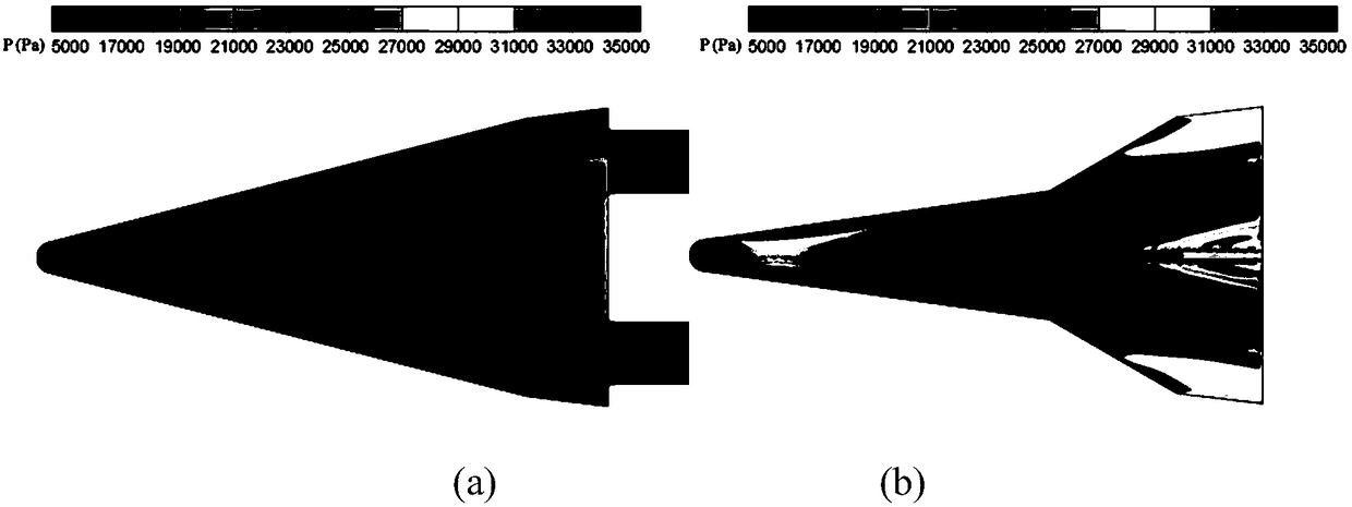
[0028] The invention discloses a rotary aircraft based on a novel flap rudder surface, which is a rotary aircraft based on a ball-cone configuration. The aircraft has a new flap-type control surface. By designing four pieces of X-shaped distributed flaps at the tail of the rotary aircraft, and using the flaps as the full-motion rudder surface of the aircraft, the aircraft can achieve hypersonic speed by deflecting the flaps. lower maneuverability. The new flap rudder surface replaces the conventional empennage layout scheme, which helps to slow down or eliminate the problems of aerodynamic interference and aerodynamic heating in the conventional empennage layout scheme, and effectively increases the loading space inside the aircraft. In the present invention, the novel flap-type control rudder is installed at the bottom of the spun fuselage,...


PUM


Abstract

A rotary aircraft based on a new type of flap rudder is based on a sphere-conical configuration of a rotary aircraft. This aircraft has a new type of flap control rudder surface. By designing four x-shaped distributed flaps on the tail of the body of rotary aircraft, and using the flaps as the full-motion rudder surface of the aircraft, the maneuverability of the aircraft at hypersonic speed can be obtained by flap deflection. The new type of flap rudder surface, replacing a common tail layout scheme, is helpful to reduce or eliminate the aerodynamic interference and heating problems in the conventional tail-fin configuration scheme, and effectively increase the loading space inside the aircraft instead of conventional tail-fin configuration scheme. The novel flap type control rudder is arranged at the bottom of the body of revolution fuselage, the flow of the flap rudder surface under the hypersonic environment will not affect the flow of the upstream body of revolution fuselage, theaerodynamic interference between the flap rudder and the body of the aircraft fuselage is small, and the problem of mutual interference between the tail fins of the conventional body of revolution fuselage is effectively avoided.

Description

technical field [0001] The invention is a rotary aircraft based on a novel flap rudder surface, which belongs to the field of aerodynamic layout design of hypersonic aircraft. Background technique [0002] Ballistic missiles, as the basis for a country to maintain medium and long-range strike capabilities, are the focus of the research and development of weapons and equipment by major military powers in the world. With the rapid development of anti-missile technology in recent years, the inertial re-entry flight of traditional ballistic missiles has become difficult to break through the interception of current anti-missile systems. At present, countries around the world are seeking re-entry weapon systems that are more mobile and capable of penetrating defenses. Therefore, it is very urgent to develop a new type of reentry vehicle with high maneuverability. [0003] The layout of conventional reentry vehicles mostly adopts the ball-cone structure. At present, this type of ...

Claims


Application Information

Patent Timeline
Patent Type & Authority Applications(China)
IPC IPC(8): B64G1/62B64G1/22
CPCB64G1/62B64G1/22
Inventor 刘强龚安龙周伟江纪楚群
Owner CHINA ACAD OF AEROSPACE AERODYNAMICS
Why Eureka
Try Eureka