Tire type tunnel track laying crane and construction method

A crane and tire-type technology, applied in the directions of walking bridge cranes, cranes, traveling mechanisms, etc., can solve the problems of low construction efficiency and segment damage, and achieve the goal of simplifying construction steps, reducing construction costs, and reducing construction workload. Effect

Pending Publication Date: 2019-01-04
CHINA RAILWAY ENG MASCH RES & DESIGN INST CO LTD
View PDF0 Cites 8 Cited by
  • Summary
  • Abstract
  • Description
  • Claims
  • Application Information

AI Technical Summary

Problems solved by technology

[0004] The purpose of the present invention is to provide a tire-type tunnel track-laying crane and a construction method to solve the technical problems that the existing technology can only adapt to a single section size, and laying temporary rails in the tunnel will cause great damage to the segments and low construction efficiency. The whole tire-type running mode can realize the construction of different sections in the tunnel including tunnels, platforms, civil air defense doors, etc., simplify the construction steps, improve the production efficiency of the operation, and reduce the damage caused by the temporary rail to the segments

Method used


Image

  • Tire type tunnel track laying crane and construction method
  • Tire type tunnel track laying crane and construction method
  • Tire type tunnel track laying crane and construction method

Examples


Embodiment Construction

[0038] The technical solutions of the present invention will be further specifically described below through the embodiments and in conjunction with the accompanying drawings.

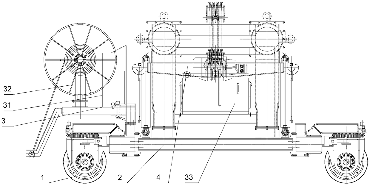
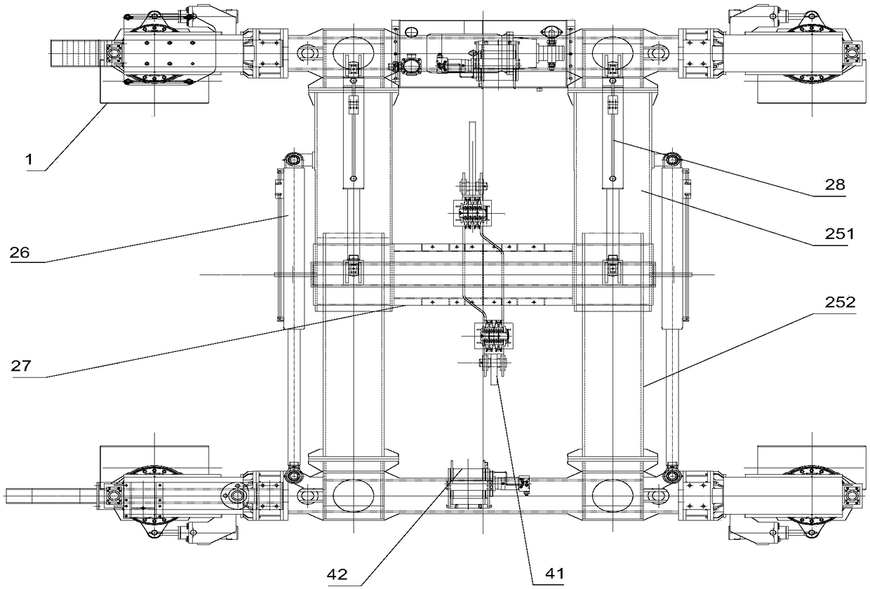
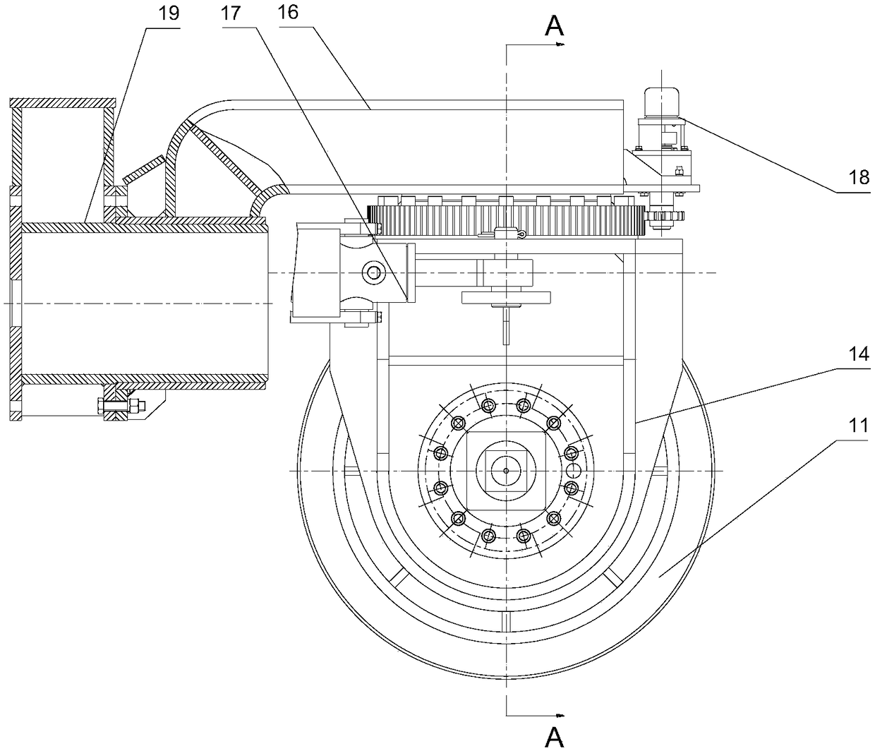
[0039] like Figure 1 to Figure 6 As shown, the present invention discloses a tire-type tunnel track-laying crane, which may include a wheel set 1, a door frame 2, a workbench 3 and a lifting device 4, and the wheel sets 1 are multiple and are respectively arranged on the door frame 2 Around the bottom, the door frame 2 is operated by each wheel set 1, and the workbench 3 can include a console 31, a power supply device 32 and a hydraulic device 33, and the console 31 and the power supply device 32 are installed on one of them respectively. On the wheel set 1, the hydraulic device 33 is installed and fixed on the door frame 2, the lifting device 4 includes a spreader 41 and a winch 42, and the winch 42 is fastened to the door frame 2, and connected by a wire rope. Said spreader 41.

[0040] Wherein, e...


PUM


Abstract

The invention discloses a tire type tunnel track laying crane and a construction method. The crane comprises wheel groups, a gantry, a working platform and a lifting device, wherein the wheel groups are arranged around the bottom of the gantry respectively; the working platform comprises a console, a power supply device and a hydraulic device; the console and the power supply device are respectively mounted on one wheel group; the hydraulic device is fixedly mounted on the gantry; the lifting device comprises a lifting appliance and a winch; the winch is fastened on the gantry and is linked with the lifting appliance through a steel wire rope. The construction method comprises the following steps: carrying out preparation before construction, constructing a shield tunnel, and carrying outtransferring operation. By adopting the tire type tunnel track laying crane, the technical problems that the prior art is only applicable to a single cross section size, tube pieces are greatly damaged if a track is temporarily laid in a tunnel, and the construction efficiency is low, can be solved, a whole-process tire type walking mode is achieved, construction of different cross sections such as tunnels, platforms and defense doors in tunnels can be achieved, construction steps can be simplified, the working and production efficiency can be improved, and damage of temporary tracks to tube sheets can be also reduced.

Description

technical field [0001] The invention relates to a crane and a construction method, belonging to the field of engineering equipment, in particular to a tire-type tunnel track-laying crane and a construction method. Background technique [0002] At present, the construction of various types of subway track-laying gantry cranes generally adopts the whole process of laying temporary running tracks with different gauges. First, the bottom plate of the steel pier is fixed on the platform and the bottom plate of the tunnel with expansion bolts, and the height of the steel pier is adjusted to the construction requirements. position, the upper plate of the steel pier is fastened to the bottom plate of the rail with bolts, the track-laying gantry cranes operate in pairs, and the construction work is carried out on the temporary track in the way of lifting the rail. The segments will be destroyed during the above construction, laying and dismantling the temporary track will endanger th...

Claims


Application Information

Patent Timeline
Patent Type & Authority Applications(China)
IPC IPC(8): B66C17/06B66C5/02B66C9/14B66C6/00
CPCB66C5/02B66C6/00B66C9/14B66C17/06
Inventor 李文豪罗璞程凤于分超李玮徐军马朝晖郑欢杨顺付鹏牛壮壮
Owner CHINA RAILWAY ENG MASCH RES & DESIGN INST CO LTD
Why Eureka
Try Eureka