Multifunctional road sweeper

A road sweeper and multi-functional technology, applied in road cleaning, construction, cleaning methods, etc., can solve the problems of easy overloading of the anti-collision element 40, overturning of the garbage collection device, and high risk of damage, so as to avoid dust flying and clean up. Effect

Active Publication Date: 2019-01-04
SHANGHAI XIANTU INTELLIGENT TECH CO LTD
View PDF9 Cites 5 Cited by
  • Summary
  • Abstract
  • Description
  • Claims
  • Application Information

AI Technical Summary

Problems solved by technology

[0003] For the brush anti-collision device, the authorized announcement number 207254805U utility model patent discloses a cleaning width automatic adjustment mechanism, the width adjustment is limited by the induction of the anti-collision wheel, the sensitivity of the mechanism is poor, and the swivel brush connected to the rotating arm is easy to break off during high-speed impact , so this kind of mechanism is difficult to meet the high-speed impact; the invention patent of the authorized notification number CN107806047A also discloses the anti-collision member 40, when it encounters an obstacle, the cleaning mechanism rotates relative to the obstacle, avoids or pushes aside the obstacle, and the obstacle cannot be removed. When moving, the vehicle must be avoided, and the anti-collision member 40 is used as a support. Obviously, the anti-collision member 40 is easily overloaded at this time, and the risk of damage is high; the new patent of the authorized announcement number CN205776012U relies on the anti-collision device composed of a limit block and a spring to prevent collision. However, a single spring will suddenly elongate when it receives a severe and rapid impact. One will cause damage to the spring, and the other will damage the swing arm when it rebounds. New type, so I won’t go into details here; most of the existing anti-collision devices on the market are basically as described in the above patents, the spring tightens the swing arm, and the limit block is used to limit the position, the spring is easy to strain, the swing arm is easily damaged, and it is difficult to deal with sudden collision
[0004] For the garbage collection device, at present, the lifting device of the garbage collection device of the road sweeper adopts the method that the two ends of the oil cylinder are respectively hinged to the frame and the garbage collection device. The lifting of the garbage collection device; although it can meet the general lifting requirements, there are the following problems in use: 1. During the walking process after lifting, the garbage collection device will impact and collide with the oil cylinder, and the use of the oil cylinder under high load will shorten the service life of the oil cylinder; The second is that the center of gravity of the car is moved up after the garbage collection device is raised, and there is a great potential safety hazard when walking; the invention patent patent application publication number of CN106544973A discloses a road sweeper lifting device and a road sweeper. The way of the buffer device can overcome the impact and collision of the collecting device on the oil cylinder, but it still cannot solve the problem of moving the center of gravity upward; the application publication number is CN 106192825A. By improving the frame and using a larger frame with a stronger load-bearing capacity, the lifting safety is guaranteed. The problem of moving the center of gravity upwards still exists; in addition, in the existing road sweeper garbage cleaning system, the garbage discharge outlet of the garbage collection device is mostly at the upper end, and the garbage collection device needs to be turned over when unloading the garbage, and there is a hidden danger of overturning when the garbage collection device is heavy Of course, the existing cleaning system also has some deficiencies in cleaning effect, dust removal, filtration, absorption of roadside gravel and other sundries, etc.

Method used


Image

  • Multifunctional road sweeper
  • Multifunctional road sweeper
  • Multifunctional road sweeper

Examples


Embodiment Construction

[0034] In order to deepen the understanding of the present invention, the multifunctional road sweeper sweeping brush anti-collision device of the present invention will be further detailed below in conjunction with examples and accompanying drawings. This embodiment is only used to explain the present invention and does not constitute a limitation to the scope of protection of the present invention. .

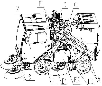
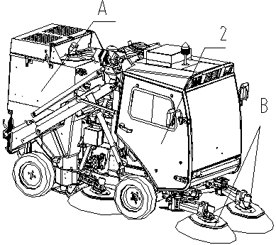
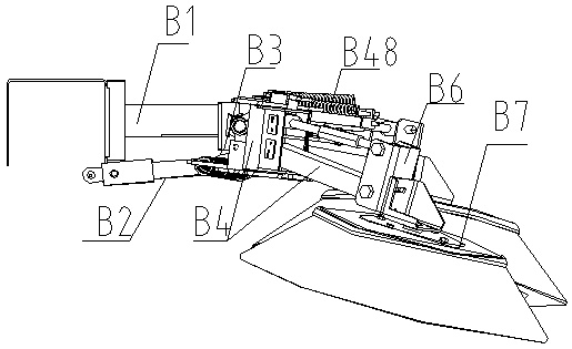
[0035] Such as Figure 1 to Figure 15 It shows an embodiment of the sweeping brush anti-collision device of a multifunctional road sweeper. A multifunctional road sweeper includes a vehicle frame 1, a cab 2 located at the front end of the vehicle frame, and a garbage collector located at the rear end of the vehicle frame. Assembly A, the sweeping brush anti-collision device B installed at the front end and the middle of the frame, the frame between the driver's cab and the garbage collection assembly is equipped with a power assembly C, a cooling and air supply system D, and a...


PUM


Abstract

The invention discloses a multifunctional road sweeper, comprising a vehicle frame, a cab arranged at the front end of the vehicle frame, a garbage collection assembly arranged at the rear end of thevehicle frame, a sweep brush anti-collision device arranged at the front end of the vehicle frame and the middle part of the vehicle frame, a power assembly and a heat-dissipating air supply system arranged on the vehicle frame between the cab and the garbage collection assembly, and an oil tank. The sweep brush anti-collision device comprises a bracket, an oil cylinder, a sweeping brush frame, anoil cylinder block articulate with one end of that bracket, and an oil cylinder rod articulated with one end of the sweeping brush frame. The other end of the sweeping brush frame is connected with the other end of the bracket. A sweep brush is arranged on that sweep brush frame, and the sweeping brush comprises a cross beam and a swing arm hinged on the cross beam. An outer tension spring and aninner tension spring of the brush anti-collision device are arranged to control the movement range of the swing arm, and the positioning slot is clamped on the pin shaft to complete the positioning,thereby realizing the soft connection of the swing arm. When the pin shaft is impacted, the pin shaft is separated from the positioning groove, thus avoiding the damages of the spring, the swing arm,the sweeper plate and other structures on the swing arm, and achieving good anti-collision effect.

Description

technical field [0001] The invention relates to the technical field of garbage cleaning vehicles, in particular to a vehicle for cleaning road garbage and sundries, in particular to a multifunctional road sweeper. Background technique [0002] Electric sweeper (Electric sweeper), as one of the sanitation equipment, is an automatic cleaning all-in-one machine that combines road vacuuming, sweeping, water spraying, and garbage transportation. It is a new type of efficient cleaning equipment used in outdoor environments. The electric road sweeper is suitable for outdoor cleaning in parks, sanitation, cleaning companies, property management companies, squares, universities, highways, and squares. [0003] For the brush anti-collision device, the authorized announcement number 207254805U utility model patent discloses a cleaning width automatic adjustment mechanism, the width adjustment is limited by the induction of the anti-collision wheel, the sensitivity of the mechanism is p...

Claims


Application Information

Patent Timeline
Patent Type & Authority Applications(China)
IPC IPC(8): E01H1/08
CPCE01H1/0845
Inventor 郝秀成秦涛谢云龙
Owner SHANGHAI XIANTU INTELLIGENT TECH CO LTD
Why Eureka
Try Eureka