A self-righting cast-in-situ pile swinging device

A technology of self-righting and cast-in-situ piles, which is applied in sheet pile walls, buildings, and foundation structure engineering, etc., can solve the problems of affecting the verticality of the building or setting the included angle, affecting the aesthetics of the building, and the limited range of the included angle, etc., to achieve good insertion Connecting effect and strength, ensuring the plugging effect and strength, and improving the effect of precision

Active Publication Date: 2021-02-26
福建中冶永行集团有限公司
View PDF10 Cites 0 Cited by
  • Summary
  • Abstract
  • Description
  • Claims
  • Application Information

AI Technical Summary

Problems solved by technology

[0002] With the rapid expansion of urbanization, high-rise buildings need to be built on different ground surfaces, and the inclination angles of different grounds and land conditions are different; when high-rise buildings are built, foundation structures such as piles must be placed to ensure strength; the pile driver is generally fixed on the ground surface for compaction, so the angle range between the ground pile and the ground is relatively limited, so for the situation where the ground is relatively inclined, additional positioning and calibration of the pile is required; Moreover, with different soil hardness, after the piles are rammed, the soil will also release a certain amount of stress, causing the piles to tilt; in addition, the traditional piles can only be adjusted to be parallel to the gravity line, and cannot be accurately adjusted according to different ground angles. Adjustment; thus it is easy to affect the verticality of the entire building relative to the ground or set the included angle, thereby affecting the aesthetics of the building

Method used


Image

  • A self-righting cast-in-situ pile swinging device
  • A self-righting cast-in-situ pile swinging device
  • A self-righting cast-in-situ pile swinging device

Examples


Embodiment Construction

[0028] The present invention is described in further detail now in conjunction with accompanying drawing. These drawings are all simplified schematic diagrams, which only illustrate the basic structure of the present invention in a schematic manner, so they only show the configurations related to the present invention.

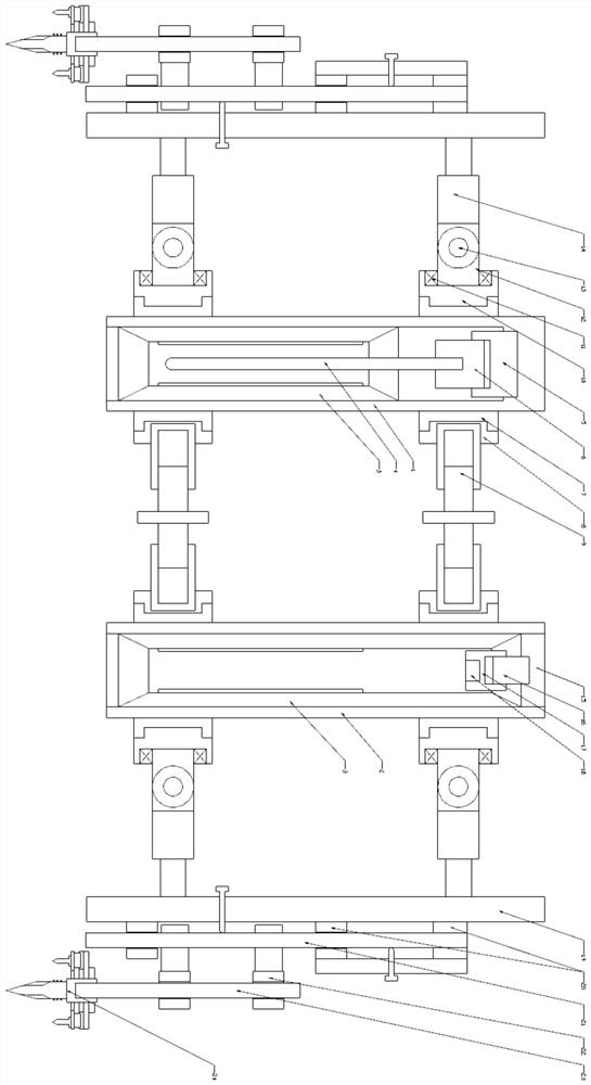
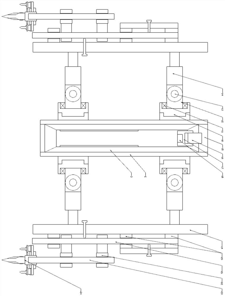
[0029] Such as figure 1 As shown, it is a single row and two column pile structure, which only includes a pile array composed of a standard pile sleeve and a positioning pile sleeve; the positioning pile sleeve and the standard pile sleeve are connected by a supporting frame, and the periphery of the supporting frame is passed through The pin assembly is connected to the ground; the standard pile sleeve is provided with a standard pile hole, the top of the standard pile sleeve passes through a connecting seat, and a lifting seat is threaded on the connecting seat, and the end of the lifting seat is vertically fixed to the insertion rod; The positioning pile s...


PUM


Abstract

The invention relates to a pile swinger for self-righting cast-in-situ piles, which comprises a pile array composed of several positioning pile sleeves and several standard pile sleeves; the positioning pile sleeves and the standard pile sleeves are connected through a support frame, and the periphery of the support frame is connected with a pin assembly. Ground connection; the top of the standard pile sleeve is connected with a plug-in rod; the top of the positioning pile sleeve is provided with a pile connection hole; the support frame includes an end connecting sleeve sleeved at both ends of the standard pile sleeve and the positioning pile sleeve; The positioning pile sleeve and the standard pile sleeve are connected by a fixed connector. The fixed connector includes two connection platforms A for fixed connection with the end connection sleeve. The connection platforms A are connected by a telescopic mechanism A; the support frame also It includes a number of peripheral connecting columns, which are connected to the positioning pile sleeves and standard pile sleeves on the periphery of the pile array through adjustment connectors. The adjustment connectors include universal connectors and telescopic mechanisms B; Peripheral connection posts.

Description

technical field [0001] The invention relates to a pile swinger for self-righting cast-in-place piles, which belongs to the field of construction equipment. Background technique [0002] With the rapid expansion of urbanization, high-rise buildings need to be built on different ground surfaces, and the inclination angles of different grounds and land conditions are different; when high-rise buildings are built, foundation structures such as piles must be placed to ensure strength; the pile driver is generally fixed on the ground surface for compaction, so the angle range between the ground pile and the ground is relatively limited, so for the situation where the ground is relatively inclined, additional positioning and calibration of the pile is required; Moreover, with different soil hardness, after the piles are rammed, the soil will also release a certain amount of stress, causing the piles to tilt; in addition, the traditional piles can only be adjusted to be parallel to ...

Claims


Application Information

Patent Timeline
Patent Type & Authority Patents(China)
IPC IPC(8): E02D13/04
CPCE02D13/04
Inventor 倪行干张秀成汪长仁
Owner 福建中冶永行集团有限公司
Why Eureka
Try Eureka