
Pipe gallery building comprehensive optimal design based on BIM

An optimized design and pipe gallery technology, which is applied in construction, infrastructure engineering, water conservancy projects, etc., can solve the problems of earthquake dislocation, poor seismic effect, easy to damage cables, etc., and achieve the effect of avoiding earthquake dislocation

Active Publication Date: 2019-01-04
UNIV OF SCI & TECH LIAONING
View PDF6 Cites 2 Cited by
  • Summary
  • Abstract
  • Description
  • Claims
  • Application Information

AI Technical Summary

Problems solved by technology

The fault position of the concave structure is 90 degrees, and the cables in the pipe gallery are mostly thick cables, and then multiplied by multiples (10 times, 15 times, 20 times, 30 times), which leads to the fault position of the concave structure in many cases. The cable installation is not standardized, so that the turning radius is too small, and because the cable turning angle is too small, it is easy to damage the cable during use
[0004] There is no limit device at the section of this concave structure, and the anti-seismic effect is extremely poor. The pipe gallery width direction is prone to earthquake dislocation. After the earthquake dislocation, the sealing effect is greatly reduced, and water seepage inside the pipe gallery occurs.

Method used


Image

  • Pipe gallery building comprehensive optimal design based on BIM
  • Pipe gallery building comprehensive optimal design based on BIM
  • Pipe gallery building comprehensive optimal design based on BIM

Examples


Embodiment Construction

[0022] Below in conjunction with specific embodiment, further illustrate the present invention. It should be understood that these examples are only used to illustrate the present invention and are not intended to limit the scope of the present invention. In addition, it should be understood that after reading the content taught by the present invention, those skilled in the art may make various changes or modifications to the present invention, and these equivalent forms also fall within the scope defined in the present application.

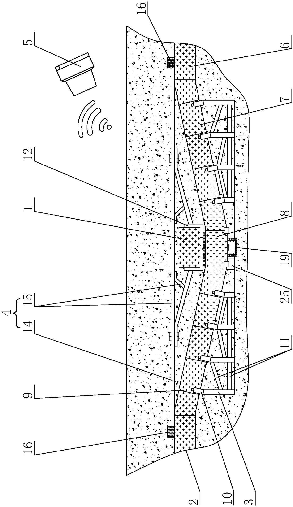
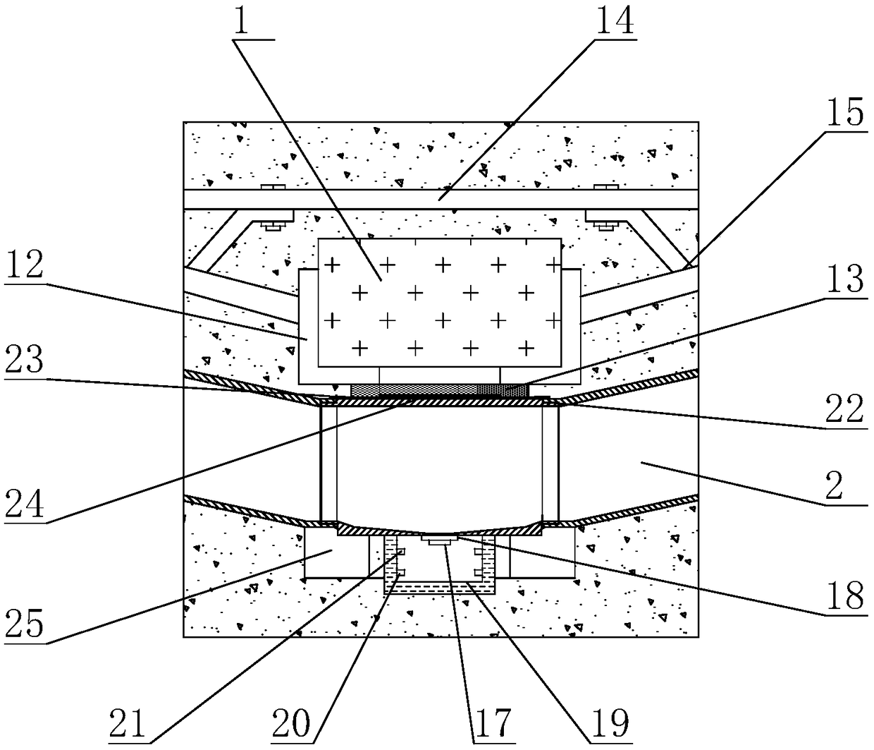
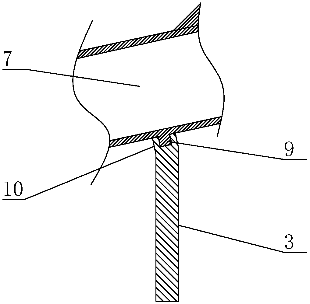
[0023] The present invention is based on the BIM-based comprehensive optimization design of the pipe gallery building. The main structure includes the first pipe gallery 1, the second pipe gallery 2 intersecting the first pipe gallery 1 at a certain angle, and the bottom pipe gallery limit support frame. 3. The limit support frame of the top pipe gallery 4. The remote computer control system 5;

[0024] The second pipe gallery 2 includes a top ...


PUM


Abstract

The invention discloses a pipe gallery building comprehensive optimal design based on a BIM and mainly relates to the technical field of underground pipe gallery buildings. The pipe gallery building comprehensive optimal design comprises a first pipe gallery, a second pipe gallery, a bottom pipe gallery limiting supporting frame, a top pipe gallery limiting supporting frame and a remote computer control system. The second pipe gallery comprises a top horizontal gallery section, an inclined transition gallery section and a bottom horizontal gallery section. A drainage opening is formed in the bottom face of the bottom horizontal gallery section, a drainage pipeline is arranged on the bottom face of the bottom horizontal gallery section, and a first alarm water level sensor and a second alarm water level sensor are arranged on the side face of the drainage pipeline and are both in signal connection with the remote computer control system. The pipe gallery building comprehensive optimal design has the beneficial effects that the pipe gallery building comprehensive optimal design is suitable for the staggered position of two sections of underground pipe gallery structures, drainage inthe pipe galleries can be more conveniently conducted, real-time alarm monitoring can be conducted, the pipe gallery building comprehensive optimal design can meet the minimum turning radius demand ofvarious cables, and the phenomenon that the pipe galleries are shocked and consequently staggered in the width direction is well avoided.

Description

technical field [0001] The invention relates to the technical field of underground pipe gallery construction, in particular to the comprehensive optimization design of pipe gallery buildings based on BIM. Background technique [0002] Underground pipe corridors are widely distributed underground in cities, as shown in the accompanying drawings Figure 4 As shown, in the prior art, this concave structure is used at the intersection of two sections of underground pipe gallery structures to avoid the intersection, and a ladder is provided at the height difference to facilitate construction workers to go up and down. However, if the intersection of the underground pipe gallery structure occurs in the river section, river section or near the sea with abundant groundwater, if water seepage occurs in the pipe gallery, this structure will easily cause water storage, and drainage is difficult, and the concave structure is blocked due to Underground water seeps through, in the accompa...

Claims


Application Information

Patent Timeline
Patent Type & Authority Applications(China)
IPC IPC(8): E02D29/045E02D29/16E02D31/02
CPCE02D29/045E02D29/16E02D31/02
Inventor 汪江杨亮王斌
Owner UNIV OF SCI & TECH LIAONING
Learn More