Hydraulic pipeline joint applied to high-pressure and high-frequency vibration environment

A high-frequency vibration and hydraulic pipeline technology, applied in the direction of pipes/pipe joints/fittings, sealing surface connection, passing components, etc., can solve problems such as potential safety hazards, lower production efficiency, waste of energy, etc., to solve leakage, enhance Sealing performance, the effect of solving oil leakage

Inactive Publication Date: 2019-01-04
孙伟
View PDF13 Cites 0 Cited by
  • Summary
  • Abstract
  • Description
  • Claims
  • Application Information

AI Technical Summary

Problems solved by technology

[0011] Leakage in industry not only reduces the efficiency of production, wastes unnecessary energy, but also brings great harm to the environment
Compared with the sealing cost required to prevent leakage, the comprehensive energy loss caused by leakage, including pollution, loss, corrosion, and downtime, is often more than 3-10 times, while the safety hazard caused by leakage is in the 10-100 times more

Method used


Image

  • Hydraulic pipeline joint applied to high-pressure and high-frequency vibration environment
  • Hydraulic pipeline joint applied to high-pressure and high-frequency vibration environment

Examples


Embodiment Construction

[0032] In order to make the object, technical solution and advantages of the present invention more clear, the present invention will be further described in detail below in conjunction with the examples. It should be understood that the specific embodiments described here are only used to explain the present invention, not to limit the present invention.

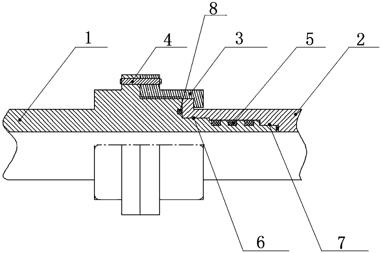
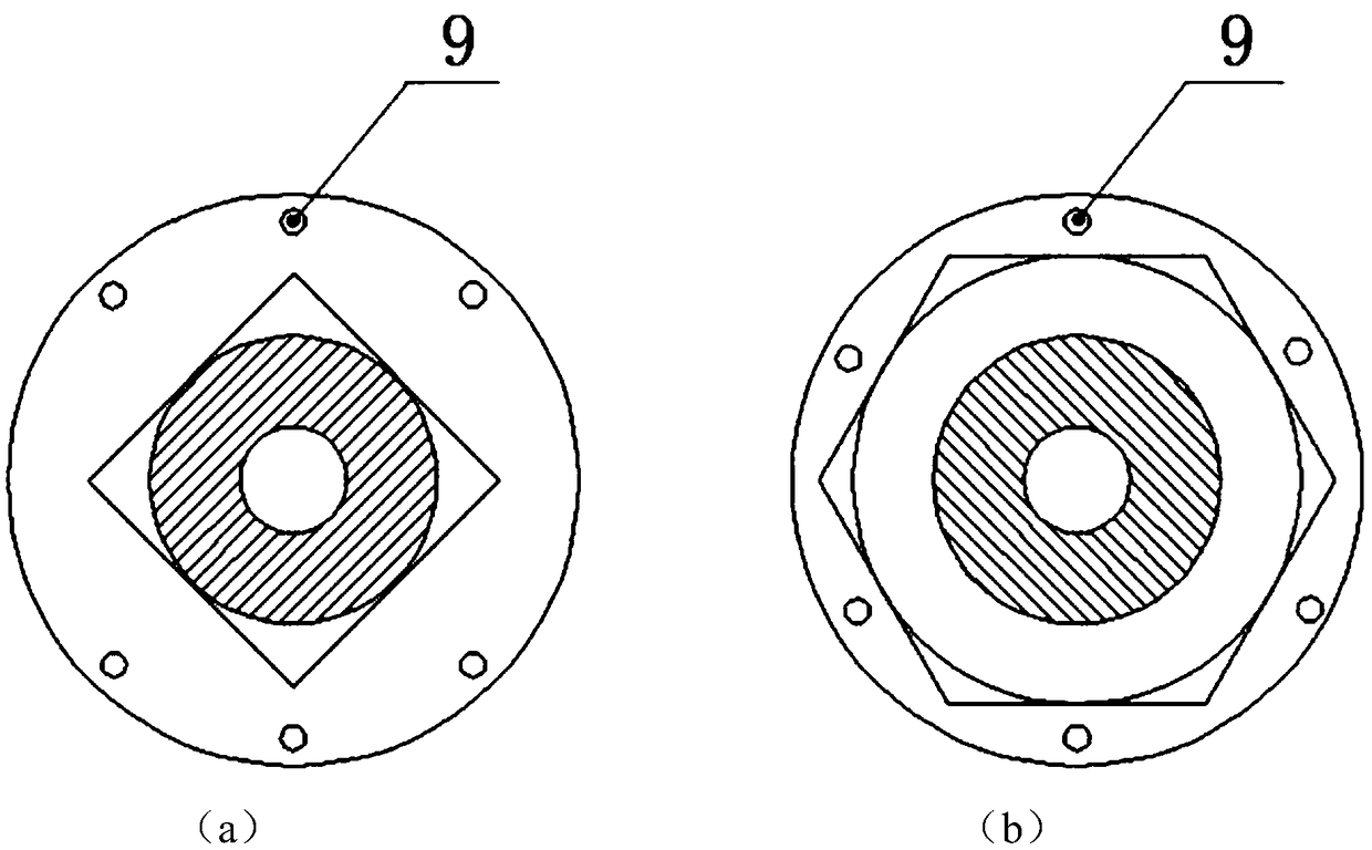
[0033] Such as figure 1 and figure 2 As shown, the hydraulic pipeline joint applied in the high-pressure and high-frequency vibration environment provided by the embodiment of the present invention includes a first body 1, a second body 2, a lock nut 3, a stop pin 4, an axial sealing strip 5, a first The brake positioning section 6, the second brake positioning section 7, the radial sealing strip 8, and the pin hole 9.

[0034] The first main body 1 and the second main body 2 are connected by interference fit, and the first main body 1 and the second main body 2 are imprisoned and connected by the lock nut 3, and the joi...


PUM


Abstract

The invention belongs to the field of hydraulic pipeline joints, and discloses a hydraulic pipeline joint applied to the high-pressure and high-frequency vibration environment. The hydraulic pipelinejoint is provided with a first main body and a second main body which are connected in an interference fit mode; the first main body and the second main body are in fastening connection through a locking nut, communicating pin holes are formed in the junction of the locking nut and the first main body, and stopping pins are arranged in the pin holes in a penetrating mode; two shaft shoulder type stopping positioning segments, namely the first stopping positioning segment and the second stopping positioning segment, are arranged at the junction of the first main body and the second main body; and an axial sealing strip and a radial sealing strip are arranged at the junction of the first main body and the second main body in a clamped mode. According to the hydraulic pipeline joint, the phenomenon of joint leakage caused by large pressure fluctuation or high-frequency vibration of the using environment is solved fundamentally, thus the hydraulic pipeline joint can indeed work stably andeffectively under the high-pressure and high-frequency vibration environment, and the phenomenon of leakage after an existing hydraulic pipeline joint is used for a period of time is solved thoroughly.

Description

technical field [0001] The invention belongs to a hydraulic pipeline joint, in particular to a hydraulic pipeline joint used in a high-pressure, high-frequency vibration environment. Background technique [0002] At present, the existing technologies commonly used in the industry are as follows: [0003] The most commonly used hydraulic pipeline joints mainly include the following two types, A-type joint: connected with the plunger hole card plate with O-shaped sealing ring; B-type joint: connected with spherical joints or conical joints with the same angle; among them, Type A The two parts of the joint are in a clearance fit during work. If there is a large pressure fluctuation or high-frequency vibration in the use environment, it will use the rod hole clamping plate as the fulcrum to make irregular movements, resulting in damage or failure of the O-ring seal. The sealing ability is reduced, which in turn causes joint leakage. When the B-type joint has large pressure flu...

Claims


Application Information

Patent Timeline
IPC IPC(8): F16L19/03F16L19/025
CPCF16L19/0212F16L19/025
Inventor 孙伟
Owner 孙伟
Why Eureka
Try Eureka