
Sound velocity profile inversion method based on underwater acoustic communication signals between network nodes

A technology of sound velocity profile and underwater acoustic communication, which is applied in the measurement of ultrasonic/sonic/infrasonic waves, propagation velocity, measurement devices, etc. It can solve the problems of low inversion accuracy and high implementation difficulty, and reduce the difficulty of equipment deployment. Guaranteed effectiveness and accuracy

Active Publication Date: 2019-01-04
INST OF ACOUSTICS CHINESE ACAD OF SCI
View PDF8 Cites 8 Cited by
  • Summary
  • Abstract
  • Description
  • Claims
  • Application Information

AI Technical Summary

Problems solved by technology

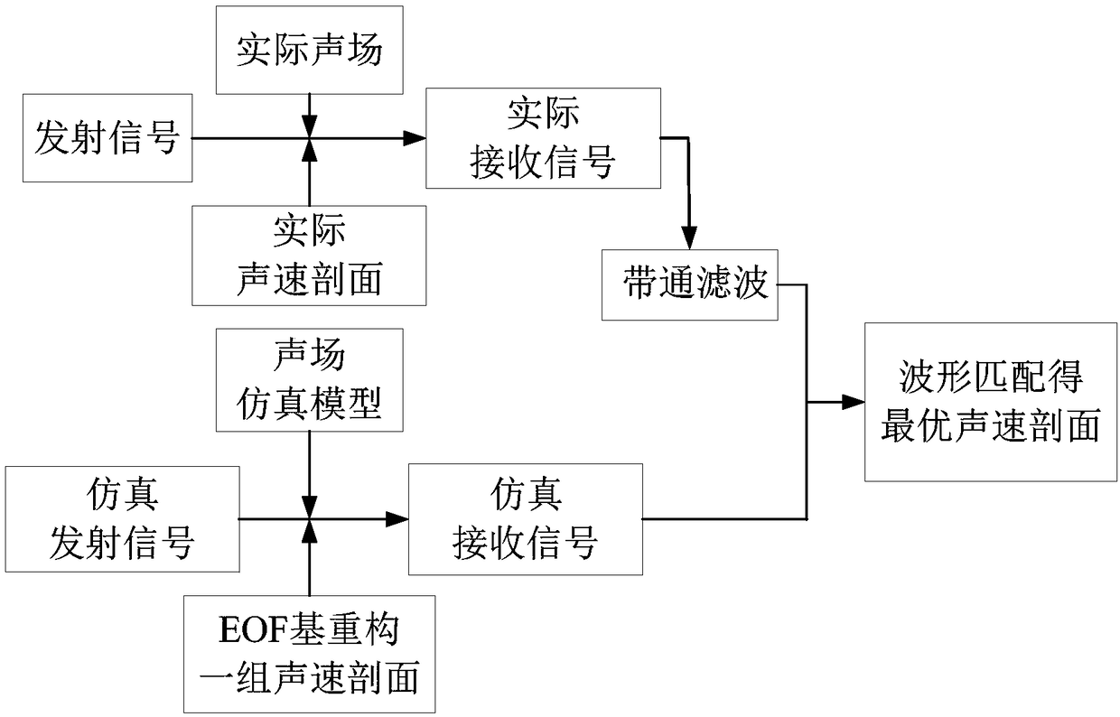
[0003] The purpose of the present invention is, in order to solve the existing technical problems of high implementation difficulty or low inversion accuracy in the existing sound velocity profile inversion method, the present invention proposes a sound velocity profile inversion method based on underwater acoustic communication signals between network nodes, This method uses the historical data of the sound velocity profile to obtain the empirical orthogonal function of the sound velocity profile (EOF, Empirical Orthogonal Function, also known as the EOF basis function), and uses the EOF basis function to further reconstruct a set of sound velocity profile values, and then calculate the reconstructed sound velocity through the sound field calculation model The received signal under the profile, and finally use the correlation between the received signal under the reconstructed sound velocity profile and the actual received signal to invert to obtain the optimal sound velocity profile

Method used


Image

  • Sound velocity profile inversion method based on underwater acoustic communication signals between network nodes
  • Sound velocity profile inversion method based on underwater acoustic communication signals between network nodes
  • Sound velocity profile inversion method based on underwater acoustic communication signals between network nodes

Examples


Embodiment 1

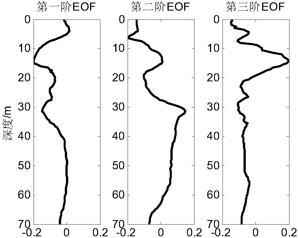
[0085] In this embodiment, taking a certain sea trial process as an example, the sound velocity profile data over a longer time period measured by the temperature chain is for comparison with the optimal sound velocity profile obtained by subsequent inversion to prove the validity of the inversion results. Accuracy and effectiveness; Utilize sound velocity profile inversion method of the present invention, the sound velocity profile history data of this sea area obtains the EOF basis function and the average sound velocity profile of test sea area (see image 3 , Figure 4 shown), Figure 4 The sound velocity profile in is the average sound velocity profile obtained by averaging the sound velocity profiles measured by CTD.

[0086] The EOF coefficients obtained by reconstructing the eight sound velocity profiles in the historical data of the sound velocity profile using the EOF basis function are shown in the following table:

[0087] EOF coefficient

[0088] Refer...


PUM


Abstract

The invention provides a sound velocity profile inversion method based on underwater acoustic communication signals between network nodes. The method includes the following steps that: step 1) a waterregion requiring sound velocity profile inversion is selected, and a sound velocity profile empirical orthogonal function is obtained on the basis of the sound velocity profile historical data of thewater region, and the empirical orthogonal function is adopted to reconstruct a set of sound velocity profiles; 2) received signals corresponding to each sound velocity profile in the step 1) are generated through simulation by means of a sound field calculation model; and step 3) correlation operation is performed on all the generated received signals in the step 2) and the underwater acoustic communication signals transmitted between the network nodes in the water region, a sound velocity profile corresponding to the highest correlation coefficient is selected as the optimal sound velocityprofile of the water region. According to the above method, the EOF (empirical orthogonal function) is obtained on the basis of the sound velocity profile historical data; and the sound velocity profile values reconstruct by the EOF are more effective sound velocity profile samples; and therefore, the validity and accuracy of inversion results can be ensured.

Description

technical field [0001] The invention relates to the technical field of underwater acoustic communication, in particular to a sound velocity profile inversion method based on underwater acoustic communication signals between network nodes. Background technique [0002] The sound velocity profile is an extremely important underwater acoustic parameter in terms of target positioning and environmental monitoring, but the method of direct on-site measurement is difficult to meet the needs of quickly obtaining the sound velocity profile in a large range of sea areas in practical applications. Therefore, the acoustic inversion method is used to The research on quickly obtaining the sound velocity profile has attracted extensive attention from scholars at home and abroad. At present, the commonly used sound velocity profile inversion methods are the matching field inversion method and the sound ray propagation time inversion method. The matching field inversion method has high requi...

Claims


Application Information

Patent Timeline
IPC IPC(8): G01H5/00
Inventor 姚美娟郭圣明贾宁鹿力成孙炳文马力
Owner INST OF ACOUSTICS CHINESE ACAD OF SCI
Learn More