Non-contact electricity-stealing prevention real-time monitoring device and method

A real-time monitoring, non-contact technology, applied in measurement devices, measurement of electrical variables, measurement of time integration, etc., can solve the problem of inability to effectively prevent non-contact electricity theft, inability to accurately locate users of electricity theft, and inability to upload electricity theft information in real time. and other problems, to achieve the effect of meeting important events and real-time requirements, alleviating the anti-stealing pressure, and reducing the scope of suspected electricity theft

Inactive Publication Date: 2019-01-04
ELECTRIC POWER RESEARCH INSTITUTE OF STATE GRID SHANDONG ELECTRIC POWER COMPANY +1
View PDF3 Cites 3 Cited by
  • Summary
  • Abstract
  • Description
  • Claims
  • Application Information

AI Technical Summary

Problems solved by technology

[0004] Aiming at the defects of the prior art, the present invention provides a real-time monitoring device and method for preventing non-contact electricity theft to solve the problem that existing ant

Method used


Image

  • Non-contact electricity-stealing prevention real-time monitoring device and method
  • Non-contact electricity-stealing prevention real-time monitoring device and method
  • Non-contact electricity-stealing prevention real-time monitoring device and method

Examples


Embodiment 1

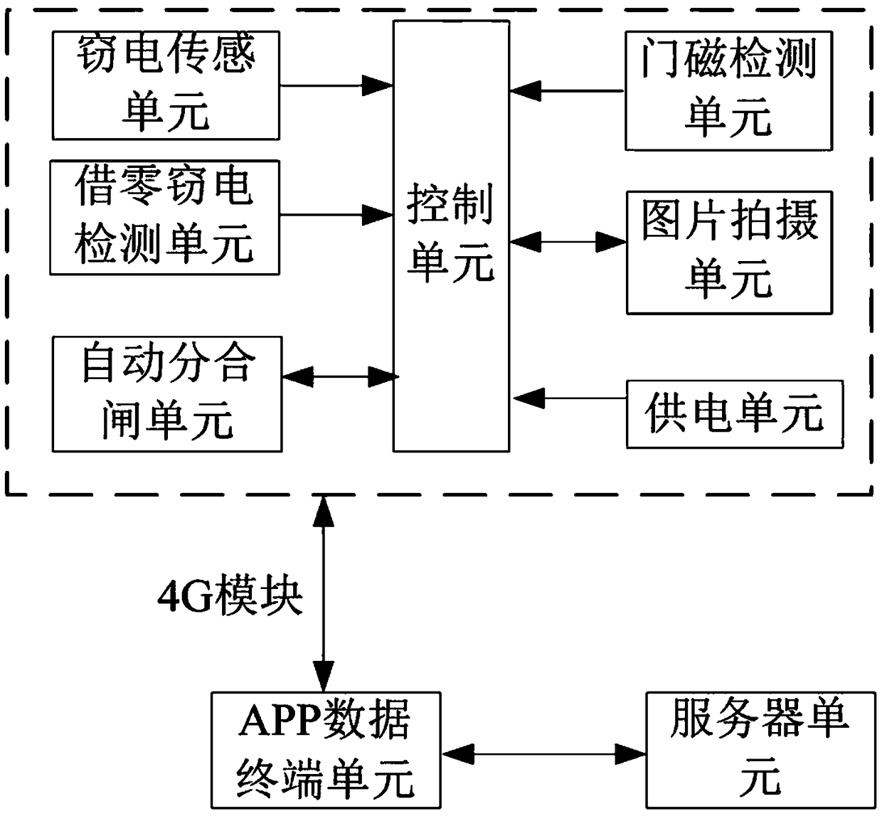
[0026] This embodiment discloses a real-time monitoring device for preventing non-contact electricity theft, such as figure 1 As shown, the device includes a control unit, a power stealing sensor unit connected to the control unit, a zero power stealing detection unit, a door magnetic detection unit, an automatic tripping and closing unit, a picture shooting unit, an APP data terminal unit and a power supply unit .

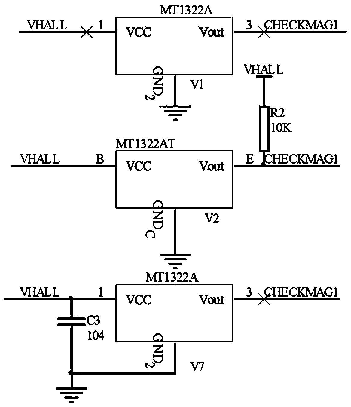
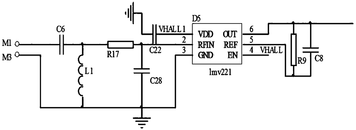
[0027] The electric stealing sensing unit includes a high-voltage electric shock detection module and a strong magnetic pulse detection module, which are used to receive external non-contact interference signals, and upload the collected interference voltage values ​​to the control unit. For the multi-surface low-voltage metering box, it can realize the separate detection of strong magnetic signals of up to 6 epitopes in three phases and 15 epitopes in single phase. For the multi-meter metering box, a strong magnetic pulse detection module is installed behind eac...

Embodiment 2

[0046] This embodiment discloses a non-contact anti-electricity theft real-time monitoring method, which includes two parts: identity authentication out-of-the-box anti-theft and non-open-box anti-theft, such as Figure 7 As shown, identity authentication to open the box to prevent electricity theft includes the following steps: S01), log in to the APP data terminal, and remotely monitor the protection status of the metering box in real time; S02), the control unit judges whether the metering box is opened according to the signal detected by the door magnetic detection unit , if the box has not been opened, then end the judgment, if the box has been opened, then judge whether it is a normal open box according to the identity information; S03), if the identity authentication is successful, the display is normal after the access control interaction, then the metering box is opened normally, and the judgment ends , if the identity authentication fails and the access control intera...


PUM


Abstract

The invention discloses a non-contact electricity-stealing prevention real-time monitoring device and method, and the device comprises a control unit, an electricity-stealing sensing unit, a zero electricity-stealing detection unit, a door magnetic detection unit, an automatic switching unit, a picture capturing unit, an APP data terminal unit and a power supply unit, wherein the electricity-stealing sensing unit, the zero electricity-stealing detection unit, the door magnetic detection unit, the automatic switching unit, the picture capturing unit, the APP data terminal unit and the power supply unit are connected with the control unit. The device and method can solve a technical problem that a conventional electricity-stealing prevention means cannot effectively prevent the non-contact electricity stealing, cannot locate an electricity theft and cannot upload the electricity-stealing information in real time.

Description

technical field [0001] The invention relates to the field of electric energy metering control, in particular to a non-contact anti-electricity theft real-time monitoring device and method for a new low-voltage metering box. Background technique [0002] For a long time, the problem of stealing electricity has always been a problem that plagues the power supply department. Due to the concealment, dispersion and diversification of electricity stealing behaviors, it is more difficult for power companies to counter electricity theft. Stealing electricity has seriously damaged the interests of electric power companies, disturbed the order of power supply and utilization, and even brought serious hidden dangers to the safety of electricity utilization. Unlike traditional energy meters, smart meters contain a large number of electronic components and are susceptible to strong electromagnetic interference. Electricity thieves take advantage of this inherent weakness of smart meter...

Claims


Application Information

Patent Timeline
IPC IPC(8): G01R11/24
CPCG01R11/24
Inventor 张志郭亮徐新光梁波孙东杜艳董贤光王平欣李付存
Owner ELECTRIC POWER RESEARCH INSTITUTE OF STATE GRID SHANDONG ELECTRIC POWER COMPANY
Why Eureka
Try Eureka