A method for registering infrared and visible light images of power computer room equipment

A technology of infrared image and visible light, which is applied in image analysis, image enhancement, graphics and image conversion, etc., and can solve problems such as unsuitable registration fields

Active Publication Date: 2019-01-04
HOHAI UNIV CHANGZHOU
View PDF3 Cites 19 Cited by
  • Summary
  • Abstract
  • Description
  • Claims
  • Application Information

AI Technical Summary

Problems solved by technology

[0005] When the equipment in the power computer room keeps working, it will not generate heat evenly as a whole, but only in a local area. Therefore, the gray distribution of the equipment in the computer room in the local area in the infrar

Method used


Image

  • A method for registering infrared and visible light images of power computer room equipment
  • A method for registering infrared and visible light images of power computer room equipment
  • A method for registering infrared and visible light images of power computer room equipment

Examples


Embodiment 1

[0053] In this embodiment, the infrared camera is located directly above the visible light camera, and the lenses of the infrared camera and the visible light camera are parallel to each other. Of course, they may also be approximately parallel. Such a setting can eliminate the difference between left and right viewing angles brought about in the process of image registration.

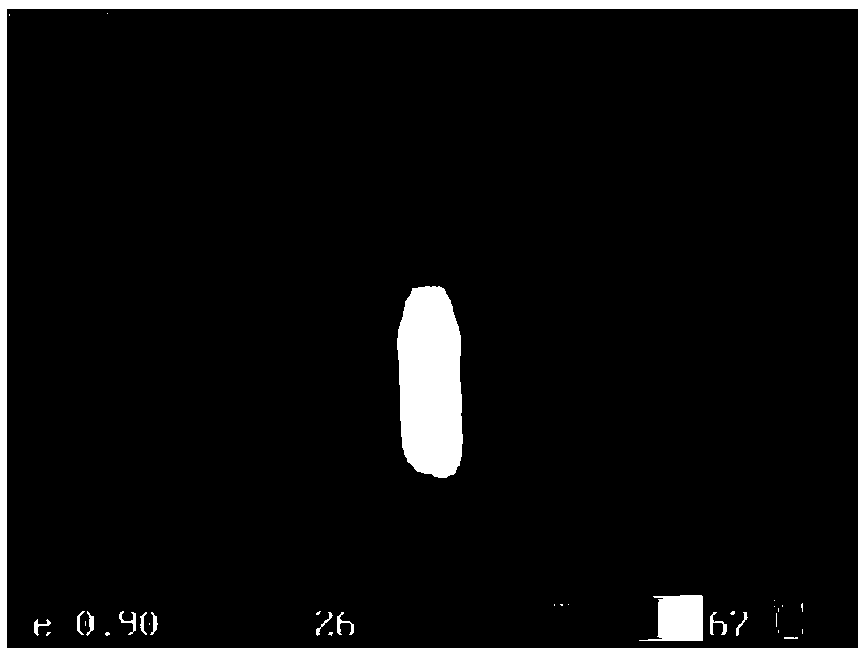
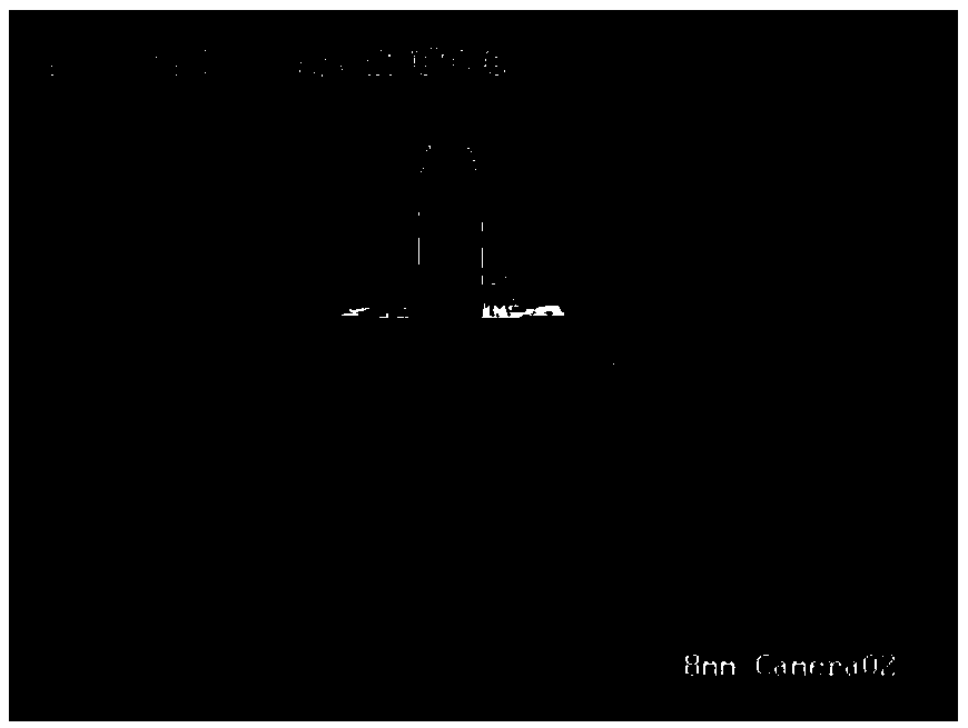
[0054] refer to Figure 2-a and Figure 2-b , the heat source calibration object of this embodiment is a dark cup filled with hot water. It is located in the central area of ​​the viewing angle range of the infrared camera and the visible light camera at the same time, so that the calibration object image is approximately located in the center of the infrared image and the visible light image at the same time.

[0055] In S2, the joint calibration parameters of the infrared and visible light cameras are calculated based on the acquired images, including:

[0056] S21, respectively acquiring the inf...

Embodiment 2

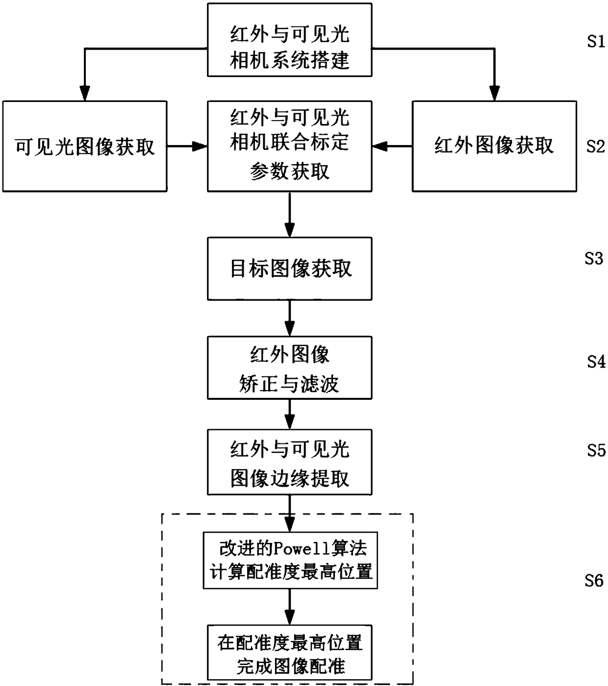
[0076] In this embodiment, the specific steps of the infrared and visible light image registration method for the equipment in the electric machine room are as follows.

[0077] 1. Infrared and visible light camera system construction.

[0078] Ensure that the infrared and visible light cameras are placed in a specific position: fix the visible light camera on the camera bracket; place the infrared camera directly above the visible light camera; adjust the orientation of the infrared camera lens so that the infrared camera lens is approximately parallel to the visible light phase lens and adjust to a suitable position Fix the infrared camera at the position to complete the construction of the infrared and visible light camera system.

[0079] 2. Acquisition of joint calibration parameters of infrared and visible light cameras.

[0080] Calculate the three calibration parameters such as rotation, scaling and translation between infrared and visible light images. The steps incl...


PUM


Abstract

The invention discloses a method for registering infrared and visible images of power machine room equipment, including infrared and visible camera system building, infrared and visible camera calibration parameters acquisition, target image acquisition, target infrared image correction, infrared and visible image edge extraction, Powell algorithm local refinement to achieve image registration andother steps. The invention calculates the calibration parameters of the infrared image and the visible image based on the camera construction mode of the specific position, and then corrects the acquired target equipment monitoring image by using the calibrated camera system. Then the edge of the image is extracted. Then the infrared image and the visible image edge image are used as the registration primitive, and the highest registration position of infrared and visible image edge is calculated, and the infrared and visible image registration is completed in this position, which can improvethe accuracy, effectiveness and practicability of temperature detection in power computer room.

Description

technical field [0001] The invention relates to the technical field of digital image processing and image registration, in particular to a registration method for infrared and visible light images of equipment in a power room. Background technique [0002] In the power system, the hardware failure of power equipment itself is one of the important reasons for large-scale power outages in the power grid. The accidents caused by equipment failure account for about half of all power grid accidents every year. As an important part of the national power grid, the power communication network is extremely technical and professional. As the hardware support of the power communication network, the power computer room equipment carries the "three remote" signals, relay protection, dispatching and administrative calls, information Services such as the intranet have very high requirements for operational stability, so it is particularly important to perform status detection on the equipm...

Claims


Application Information

Patent Timeline
IPC IPC(8): G06T7/30G06T7/80G06T7/13G06T7/136G06T7/168G06T5/00G06T3/60G06T3/40
CPCG06T3/40G06T3/60G06T5/002G06T2207/10048G06T2207/10052G06T2207/20064G06T7/13G06T7/136G06T7/168G06T7/30G06T7/80
Inventor 李庆武许金鑫马啸川
Owner HOHAI UNIV CHANGZHOU
Why Eureka
Try Eureka