A decoupling device and a MIMO antenna

An antenna and dielectric substrate technology, which is applied to antennas, antenna coupling, antenna arrays, etc., and can solve problems such as poor isolation of large-scale array antennas

Pending Publication Date: 2019-01-04
WUHAN HONGXIN TECH DEV CO LTD
View PDF8 Cites 12 Cited by
  • Summary
  • Abstract
  • Description
  • Claims
  • Application Information

AI Technical Summary

Problems solved by technology

[0005] The embodiment of the present application solves the problem of poor isolation of lar

Method used


Image

  • A decoupling device and a MIMO antenna
  • A decoupling device and a MIMO antenna
  • A decoupling device and a MIMO antenna

Examples


Embodiment Construction

[0042] In order to better understand the above-mentioned technical solution, the above-mentioned technical solution will be described in detail below in conjunction with the accompanying drawings and specific implementation methods.

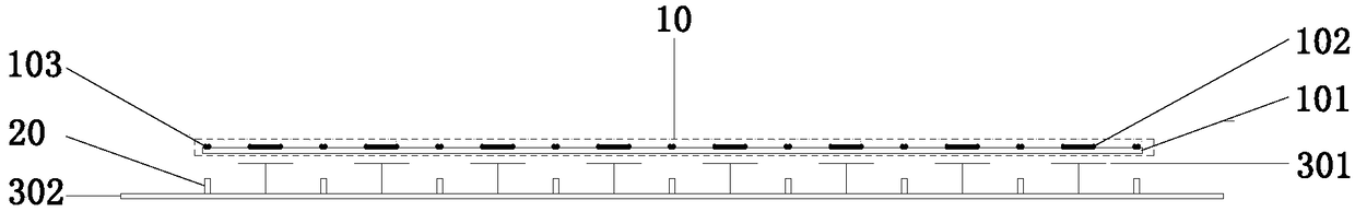
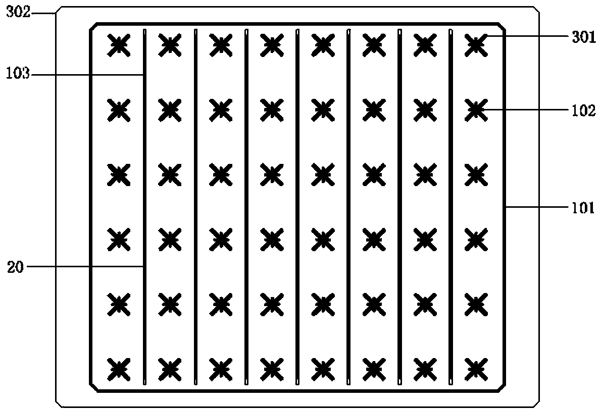
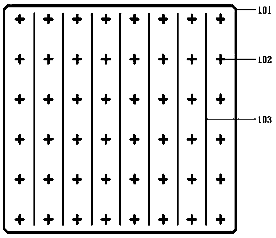
[0043] see figure 1 , figure 2 , the embodiment of the present invention provides a decoupling device for a large-scale array antenna, which mainly includes a first decoupling device 10 , and may also include a second decoupling device 20 in a preferred solution. Wherein, the first decoupling device 10 is located above the radiation element array, and the first decoupling device 10 includes a dielectric substrate 101, a guide sheet 102, and a decoupling strip 103, and the guide sheet 102, the decoupling The coupling strips 103 are all disposed on the dielectric substrate 101 , the guide sheet 102 is located directly above the radiation units 301 , and the decoupling strips 103 are located between two rows of radiation units 301 . Wherein, the ...


PUM

PropertyMeasurementUnit
Thicknessaaaaaaaaaa

Abstract

The invention belongs to the technical field of wireless communication, A decoupling device and a MIMO antenna are disclosed, The decoupling device comprises a first decoupling device, wherein the first decoupling device is positioned above the array of radiating units; the first decoupling device comprises a dielectric substrate, a lead sheet, a decoupling strip, a lead sheet and a decoupling strip are arranged on the dielectric substrate; the lead sheet is positioned directly above the radiating units; and the decoupling strip is positioned between two rows of radiating units; the decouplingdevice comprises a dielectric substrate, a lead sheet, a decoupling strip and a decoupling strip. The MIMO antenna comprises an antenna reflector, a radiation unit and a decoupling device. The invention solves the problems of poor isolation degree and pattern distortion of MIMO antennas (5G large-scale array antennas) in the prior art.

Description

technical field [0001] The invention belongs to the technical field of wireless communication, and in particular relates to a decoupling device and a MIMO antenna. Background technique [0002] With the rapid development of smart mobile terminals, wireless data traffic is increasing exponentially, and the introduction and rapid development of the Internet of Things put forward higher requirements for future wireless communication systems. [0003] In the traditional 2D-MIMO technology, the antenna generally adopts a one-dimensional linear array antenna. The small number of ports leads to a wider wave width, and the interference between base stations is more serious, and the beam direction can only be mechanically adjusted in the horizontal dimension, and the energy in the vertical dimension cannot be transferred. Centralized to the user terminal, the communication efficiency is low. Compared with the traditional 2D-MIMO technology, in the 3D-MIMO technology, the antenna ado...

Claims


Application Information

Patent Timeline
IPC IPC(8): H01Q1/52H01Q19/10H01Q21/06
CPCH01Q1/523H01Q19/104H01Q21/061
Inventor 熊锡刚骆胜军潘波
Owner WUHAN HONGXIN TECH DEV CO LTD
Why Eureka
Try Eureka