An air-bearing rotor bearingless motor with slot wedge ventilation

A bearingless motor and rotor technology, used in electrical components, electromechanical devices, electric components, etc., can solve the problems of increasing the size and complexity of the motor stator, reducing the motor efficiency and power density, and excessively long axial length. Achieve the effect of eliminating mechanical bearings, suppressing rotor temperature rise, and shortening length

Active Publication Date: 2019-01-04
HARBIN INST OF TECH
View PDF10 Cites 2 Cited by
  • Summary
  • Abstract
  • Description
  • Claims
  • Application Information

AI Technical Summary

Problems solved by technology

[0007] The purpose of the present invention is to solve the problem that the axial length of the high-speed electric spindle is too long, the stability is poor, and the bearingless motor adopts the suspension force winding to generate the magnetic pulling force, which increases the volume and complexity of the motor stator, is not conducive to the heat dissipation of the motor, and reduces the solves the problems of motor efficiency and power density, thus providing a slot-wedge ventilated air-floating rotor bearingless motor

Method used


Image

  • An air-bearing rotor bearingless motor with slot wedge ventilation
  • An air-bearing rotor bearingless motor with slot wedge ventilation
  • An air-bearing rotor bearingless motor with slot wedge ventilation

Examples


specific Embodiment approach 1

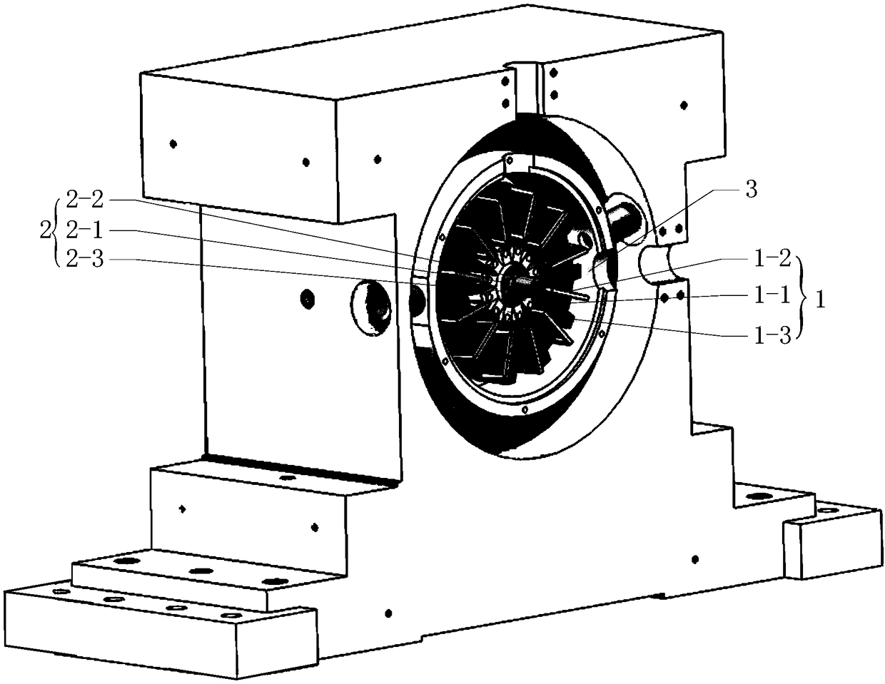
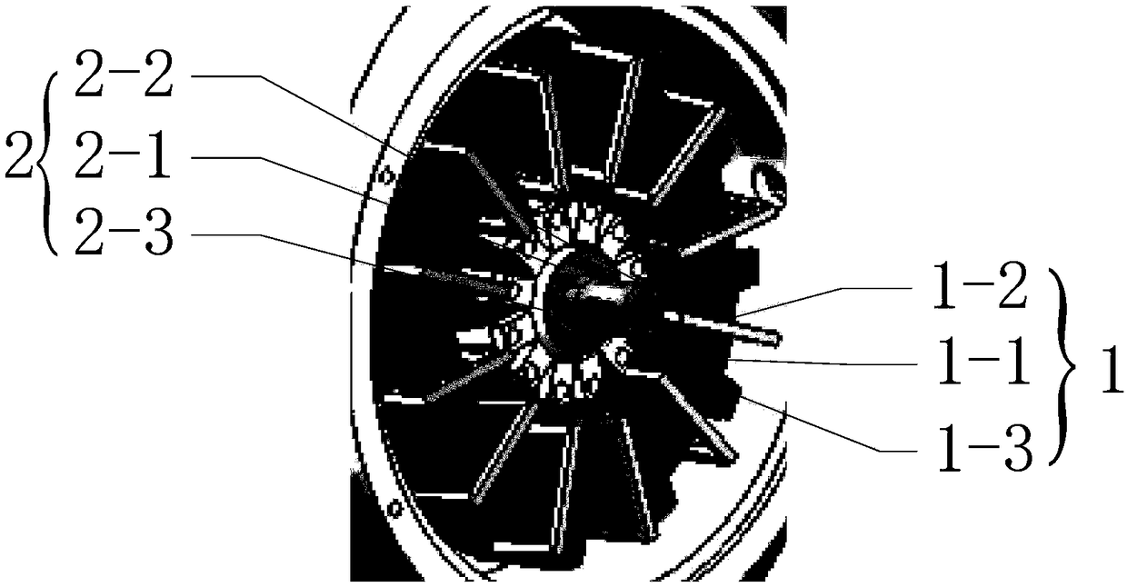
[0031] Specific implementation mode 1: Combination Figure 1 to Figure 3 Detailed description of this embodiment, a slot-wedge ventilated air-floating rotor bearingless motor described in this embodiment includes a stator 1, a rotor 2 and a casing 3;

[0032] The stator 1 is fixed in the casing 3, the rotor 2 is sleeved in the stator 1, and there is an air gap between the stator 1 and the rotor 2;

[0033] The stator 1 includes a stator core 1-1, a stator winding 1-2 and a slot wedge 1-3;

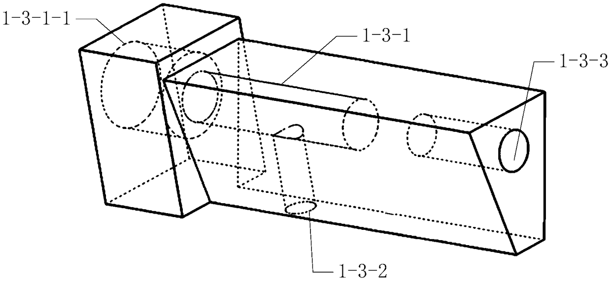
[0034] The stator core 1-1 is fixed to the casing 3. The stator core 1-1 has multiple slots evenly along the circumferential direction, each slot is provided with a stator winding 1-2, and each inner slot is fixed with a slot wedge 1 -3, the slot wedge 1-3 is provided with an air supply channel 1-3-1 and a throttle hole 1-3-2, and the throttle hole 1-3-2 communicates with the air supply channel 1-3-1 and faces the rotor 2. ;

[0035] The gas is input into the gas supply channel 1-3-1 and ejected ...

specific Embodiment approach 2

[0045] Specific embodiment 2: This embodiment is a further description of a slot wedge ventilated air-floating rotor bearingless motor described in the first embodiment. In this embodiment, the slots opened by the stator core 1-1 are open slots .

[0046] In order to ensure sufficient air supply, the diameter of the orifice 1-3-2 in the slot wedge 1-3 should be increased to produce greater suspension force. For this reason, the stator slot should be an open slot, and the slot wedge 1-3 Use magnetic slot wedges to reduce the distortion rate of the air gap magnetic field.

specific Embodiment approach 3

[0047] Specific embodiment three: This embodiment is a further description of a slot-wedge ventilated air-floating rotor bearingless motor described in specific embodiment 1. In this embodiment, the magnetizing direction of the rotor poles 2-1 is radial , In order to reduce the harmonic components of the air gap magnetic field.


PUM


Abstract

The invention relates to an air-bearing rotor bearingless motor with slot wedge ventilation, which relates to the motor field. In order to solve the problems that the axial length of a high-speed motorized spindle is too long, the stability is poor, and a magnetic pull force is generated by a suspension force winding of the bearingless motor, the volume and complexity of the motor stator are increased, which is harmful to the heat dissipation of the motor, and the efficiency and the power density of the motor are reduced. The stator core is uniformly provided with a plurality of slots along the circumferential direction, each slot is provided with a stator winding, each inner slot is fixed with a slot wedge, the slot wedge is provided with an air supply passage and a throttling hole, and the throttling hole is communicated with the air supply passage and faces the rotor; Gas is input to the air supply channel and ejected from the throttle hole to form an air floating surface between the stator and the rotor to rotate the supporting rotor; The rotor pole is attached to the outer wall of the rotor yoke. The invention is applicable to high-speed or ultra-high-speed motorized spindle systems.

Description

Technical field [0001] The invention relates to the field of motors, in particular to an air-floating rotor bearingless motor based on slot wedge ventilation. Background technique [0002] A traditional motor is composed of a stator and a rotor, which are connected by mechanical bearings. Therefore, there is mechanical friction during the rotation process. Not only there is friction torque on the rotor, but also easy to wear, generating additional mechanical vibration and noise, and shortening the service life of the motor. Bearingless motors do not have mechanical bearings, so higher speeds and longer life can be achieved. [0003] The high-speed motor spindle has the advantages of compact structure, light weight, low inertia, low noise, and fast response. It is an ideal structure in the high-speed spindle unit. With the continuous increase of the motor speed, the volume of the spindle unit gradually decreases, and the temperature rise problem is gradually severe, especially the ...

Claims


Application Information

Patent Timeline
Patent Type & Authority Applications(China)
IPC IPC(8): H02K5/16H02K3/493
CPCH02K3/493H02K5/16
Inventor 曹继伟李立毅宋禹辰陈佳亮马伊光
Owner HARBIN INST OF TECH
Why Eureka
Try Eureka