Clutch housing and clutch

A clutch housing and clutch technology, applied in clutches, friction clutches, mechanical drive clutches, etc., can solve the problems of lowering the temperature of the clutch housing, affecting the performance of the clutch, shortening the service life, etc., to prevent the entry of external impurities, and to achieve good ventilation and heat dissipation. , the effect of prolonging the service life

Active Publication Date: 2008-09-10
BYD CO LTD
View PDF0 Cites 1 Cited by
  • Summary
  • Abstract
  • Description
  • Claims
  • Application Information

AI Technical Summary

Problems solved by technology

Due to the continuous wear of the driven disc (friction disc) during the working process of the clutch, a lot of wear debris will be generated, which need to be discharged out of the clutch housing in time, otherwise it will affect the performance of the clutch, and eventually even cause damage to the clutch; the friction of the driven disc will High temperature will be generated, and the high temperature will greatly reduce the stability of the clutch work and shorten the life, so the heat in the clutch housing should be dissipated in time to reduce the temperature in the clutch housing; after a long-term use of the gearbox, a small amount of lubricating oil will pass through The oil seal at the input end of the main shaft penetrates into the clutch housing and should also be discharged out of the housing to avoid affecting the performance of the clutch; in addition, the joint surface of the clutch housing is a non-sealed surface, if external moisture penetrates into the clutch housing along the joint surface, it should also be discharged out of the housing
The clutch housings currently seen generally do not have a structure designed to discharge wear debris and oil. Some have simple straight holes designed at the bottom, which can discharge wear debris, oil liquid, and ventilate and dissipate heat. This structure also makes it easy for foreign impurities to enter the clutch housing and affect the performance of the clutch.

Method used


Image

  • Clutch housing and clutch
  • Clutch housing and clutch
  • Clutch housing and clutch

Examples


Embodiment 1

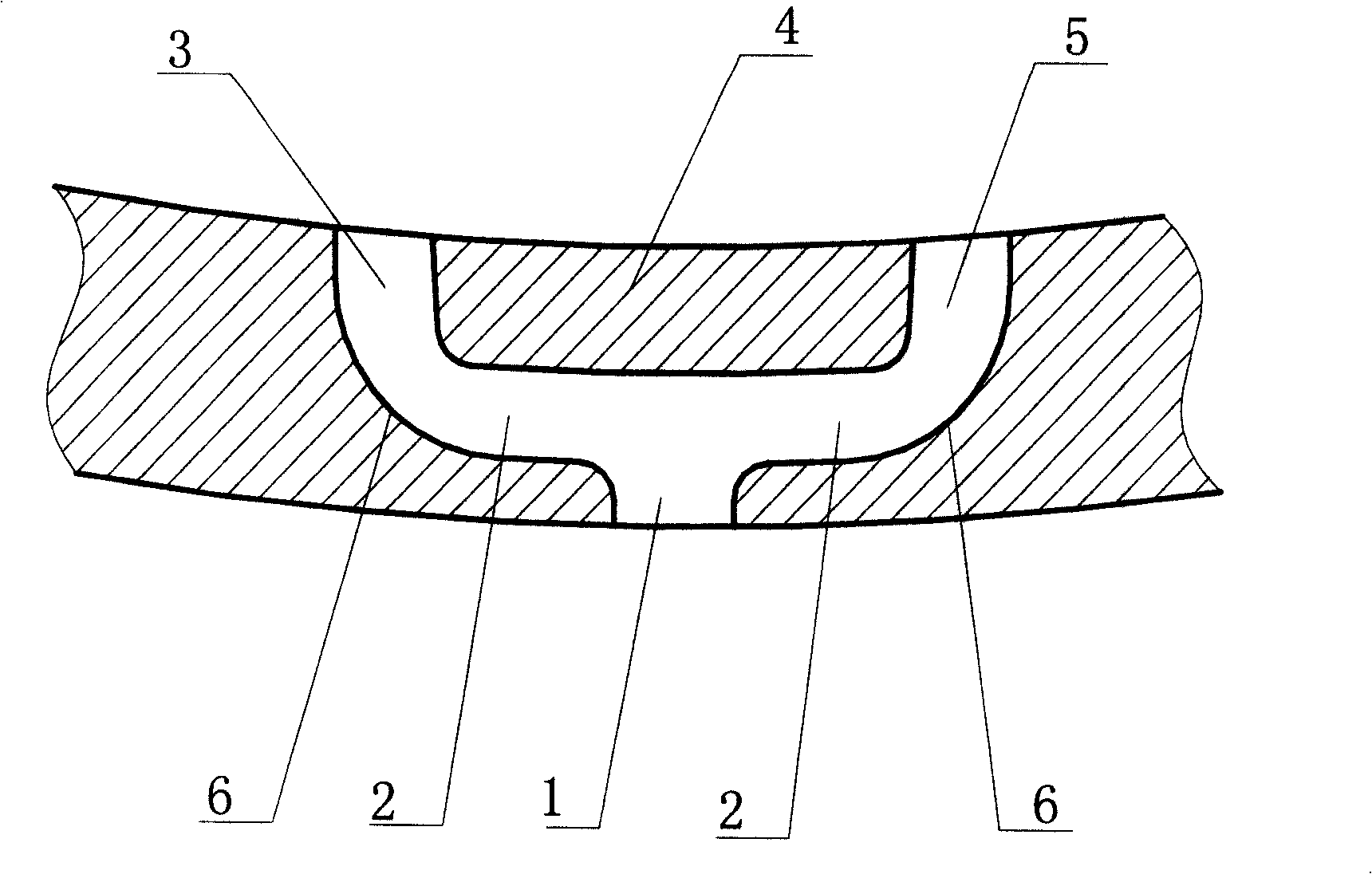
[0022] like figure 1 As shown in the figure, the cross-sectional shape of the hole in this example is approximately "Y" shape. When viewed from the outside of the clutch housing, the hole is located on the outer wall of the clutch housing with only one opening. When viewed from the inside of the clutch housing, the hole is located on the inner wall of the clutch housing. There are two openings. Open your mouth. The shorter outer channel 1 is opened on the outer wall of the clutch housing, which is opposite to the dust-blocking wall 4, and communicates with the middle channel 2 and is almost vertical. The left inner hole 3 and the right inner hole 5 are opened on the inner wall of the clutch housing.

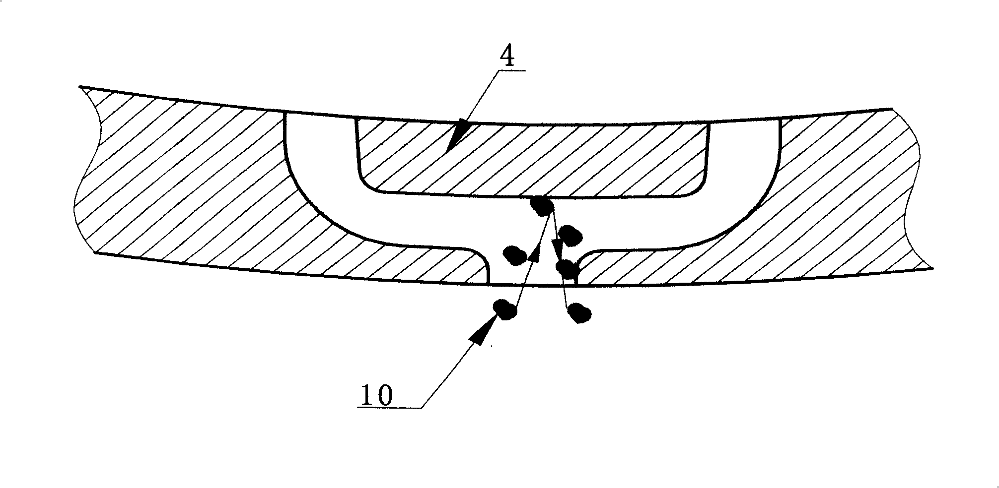
[0023] like figure 2 As shown, on the outer wall of the clutch housing, the approximately "Y"-shaped channel has only one opening, and the area communicating with the outside is small, which reduces the chance of external impurities 10 entering the outer channel 1 .

[0024] ...

Embodiment 2

[0028] like Figure 4 As shown, the shape of the hole in this example is "Y" shape. When viewed from the outside of the clutch housing, the hole is located on the outer wall of the clutch housing with only one opening. When viewed from the inside of the clutch housing, the hole is located on the inner wall of the clutch housing with two openings. The left inner channel 31 and the right inner channel 32 are opened on the inner wall 20 of the clutch housing to form a "V" shape, the outer channel 30 is opened on the outer wall 21 of the clutch housing, and one end is connected with the left inner channel 31 and the right inner channel 32 to form a "V" shape. "-shaped bottoms are connected to form a "Y"-shaped channel as a whole. Compared with the current structure with no holes or only simple straight holes on the clutch housing, it can not only discharge the wear debris of the clutch, the water and the lubricating oil infiltrated by the gearbox, but also effectively prevent exte...


PUM


Abstract

The invention discloses a clutch and a housing thereof. The housing of the clutch comprises an inner wall, an outer wall and a pore path. The pore path traverses through the inner wall and the outer wall. The entire body of the pore path is Y-shaped or similarly Y-shaped. An opening is arranged on the outer wall, while two openings are arranged on the inner wall. The structure is capable of successfully discharging grindings produced by the clutch in using process, lubricating oil infiltrated along a main shaft of a gear box, and water infiltrated from outside, is capable of effectively preventing the outside impurities from coming in, and is capable of functioning in ventilation and heat dissipation, of reducing the working temperature of the clutch, of improving the working stability of the clutch, and of prolonging the service life of the clutch.

Description

【Technical field】 [0001] The present invention relates to a clutch structure, in particular to a clutch housing structure. 【Background technique】 [0002] The clutch housing is usually a bell-shaped metal casting that connects the engine to the transmission. Most clutch housings are now integral with the transmission case, which houses the clutch assembly and supports the transmission. Due to the continuous wear of the driven disc (friction disc) during the operation of the clutch, a lot of wear debris will be generated. These wear debris need to be discharged out of the clutch shell in time, otherwise it will affect the performance of the clutch, and eventually even cause the clutch to be damaged; the friction of the driven disc will cause High temperature is generated, and high temperature will greatly reduce the stability of the clutch operation and shorten the life span, so the heat in the clutch shell should be dissipated in time to reduce the temperature in the clutch...

Claims


Application Information

Patent Timeline
Patent Type & Authority Applications(China)
IPC IPC(8): F16D13/58F16D13/72
Inventor 秦丽军陈广全黄克成
Owner BYD CO LTD
Why Eureka
Try Eureka