Ramp-error compensation circuit for peak current controlled BUCK converter

A technology of peak current control and error compensation, which is applied in the direction of converting DC power input to DC power output, adjusting electrical variables, and controlling/regulating systems. It can solve problems such as output current static errors, eliminate static errors, and ensure accuracy. Effect

Active Publication Date: 2019-01-04
BEIJING MECHANICAL EQUIP INST
View PDF7 Cites 5 Cited by
  • Summary
  • Abstract
  • Description
  • Claims
  • Application Information

AI Technical Summary

Problems solved by technology

[0007] In view of the above analysis, the embodiment of the present invention aims to provide a slope-error compensation circuit for a peak current control BUCK converter to solve the static error in the output current of the existing peak current control BUCK converter after slope compensation The problem

Method used


Image

  • Ramp-error compensation circuit for peak current controlled BUCK converter
  • Ramp-error compensation circuit for peak current controlled BUCK converter
  • Ramp-error compensation circuit for peak current controlled BUCK converter

Examples


Embodiment 1

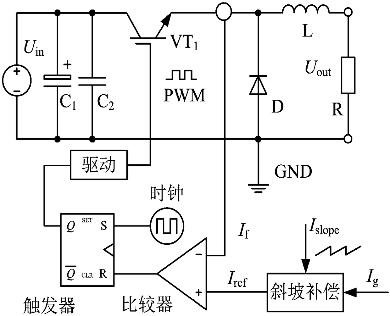
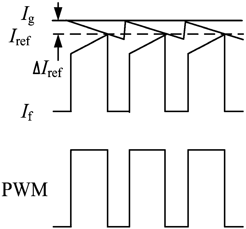
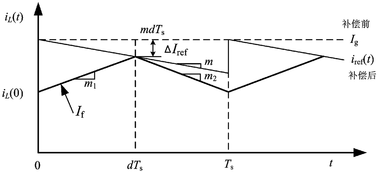
[0059] A specific embodiment of the present invention discloses an error compensation circuit for a peak current control buck converter, the connection relationship of which is as follows Figure 4 shown. The slope-error compensation circuit for the peak current control BUCK converter disclosed in this embodiment includes a slope compensation sub-circuit, an error compensation sub-circuit, and a conditioning amplifier sub-circuit. The slope compensation sub-circuit is connected in parallel with the error compensation sub-circuit, and then connected in series with the conditioning and amplification sub-circuit. A specific connection method is given below.

[0060] Specifically, the slope compensation subcircuit includes an input terminal 1, an input terminal 2, an input terminal 3 and an output terminal. Among them, the input terminal 1 receives the sawtooth wave signal output by the PWM controller, the input terminal 2 receives the bias voltage signal set by the user, the si...

Embodiment 2

[0067] Optimizing on the basis of the above examples, such as Figure 5 As shown, the slope compensation sub-circuit includes an operational amplifier module 1 and an operational amplifier module 2 connected in series in sequence. The operational amplifier module 1 is used to receive the sawtooth signal and bias voltage signal output by the PWM controller, bias and reverse the sawtooth signal output by the PWM controller, and generate an inverted sawtooth signal that changes from zero and transmit it to Op-amp module 2. The operational amplifier module 2 is configured to receive the above-mentioned inverted sawtooth signal and the current reference signal, and superimpose the inverted sawtooth signal and the current reference signal to generate a current reference signal with slope compensation.

[0068] Preferably, as Figure 6 As shown, the operational amplifier module 1 includes an operational amplifier A1 and resistors R1-R4, and the operational amplifier module 2 includ...


PUM


Abstract

The invention relates to a ramp-error compensation circuit for a peak current controlled BUCK converter, belongs to the technical field of switching power supplies and solves the problem that the output current of the peak current control BUCK converter has a static error after ramp compensation in the prior art. The ramp-error compensation circuit disclosed by the present invention comprises a ramp compensation sub-circuit, an error compensation sub-circuit and a conditioning amplifier sub-circuit, wherein the error compensation sub-circuit comprises a ramp compensation sub-circuit, an errorcompensation sub-circuit and a conditioning amplifier sub-circuit. The input signal of the error compensation sub-circuit is taken from the output voltage of the BUCK converter, and the error compensation value is proportional to the output voltage of the BUCK converter and equal to the static error of the output current of the ramp compensation sub-circuit. Therefore, the BUCK converter with anyduty cycle can achieve error compensation and eliminate the static error caused by ramp compensation.

Description

technical field [0001] The invention relates to the technical field of switching power supplies, in particular to a slope-error compensation circuit for peak current control buck converters. Background technique [0002] In the existing switching power supply control, the commonly used PWM control methods mainly include average current control and peak current control. Compared with the average current control, the transient closed-loop response of the peak current control is fast, and the transient response to the input voltage change and the output load change is also fast. It has an instantaneous peak current limiting function and can realize automatic parallel current sharing. [0003] Existing typical peak current mode PWM control such as figure 1 As shown, its characteristic signal waveform is as figure 2 As shown, the slope compensation scheme can improve the stability of the peak current control mode when the duty cycle is greater than 50%, although it solves the ...

Claims


Application Information

Patent Timeline
IPC IPC(8): H02M3/156
CPCH02M3/156
Inventor 王强季金虎胡永锋郭鑫
Owner BEIJING MECHANICAL EQUIP INST
Why Eureka
Try Eureka