LED current ripple cancellation circuit suitable for ultra-low TRIAC dimming depth

一种LED驱动、恒流控制电路的技术,应用在驱动电路领域,能够解决低呼吸式晃动、不能适配TRIAC调光器、电容体积增加等问题,达到低系统环路响应速度、优异消除输出电流纹波功能、消除呼吸式晃动的效果

Active Publication Date: 2019-01-04
DIOO MICROCIRCUITS CO LTD
View PDF4 Cites 5 Cited by
  • Summary
  • Abstract
  • Description
  • Claims
  • Application Information

AI Technical Summary

Problems solved by technology

In the prior art, in order to ensure that the power MOS transistor M1 works in the saturation region, a relatively large energy storage capacitor C1 needs to be connected externally; however, as the capacity of the energy storage capacitor C1 increases, its cost increases relatively, and the volume of the capacitor also increases. will increase significantly
However, the large-volume energy storage capacitor C1 often cannot meet the volume requirements of the new LED lamps for driving the PCB board.
[0004] At the same time, the existing technology cannot adapt to all TRIAC dimmers on the market; when a conventional TRIAC dimmer is adjusted to a depth below 5%, the matching LED lights often have a low-frequency breathing shaking phenomenon

Method used


Image

  • LED current ripple cancellation circuit suitable for ultra-low TRIAC dimming depth
  • LED current ripple cancellation circuit suitable for ultra-low TRIAC dimming depth
  • LED current ripple cancellation circuit suitable for ultra-low TRIAC dimming depth

Examples


Embodiment Construction

[0044] Specific structural and functional details disclosed herein are representative only and for purposes of describing example embodiments of the present invention. This invention may be embodied in many alternate forms and should not be construed as limited to only the embodiments set forth herein.

[0045] In the description of the present invention, it should be noted that unless otherwise specified and limited, the term "connection" should be understood in a broad sense, for example, it can be a fixed connection, a detachable connection, or an integral connection; It can be directly connected, or indirectly connected through an intermediary, or it can be an overlap between two components. Those of ordinary skill in the art can understand the specific meanings of the above terms in the present invention in specific situations.

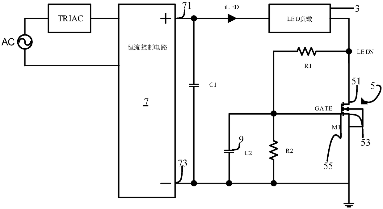
[0046] The driving circuit of the present invention is built on figure 1 shown on the LED driver system, see figure 1 , the LED drive system ...


PUM


Abstract

A drive circuit for eliminating the current ripple of an LED drive system comprises a current ripple control module, a low loop response module, an LEDN potential detection response module, a start-upquick response module and a dimming quick response module. The driving circuit has extremely low system loop response speed in a stable operation state, thereby ensuring an excellent function of eliminating output current ripple of the circuit, and eliminating the phenomenon that the LED lamp sloshes at a lower frequency under the condition of small TRIAC dimming current.

Description

technical field [0001] The present invention relates to a driving circuit for eliminating current ripple in a light-emitting diode (LED) drive system, in particular to an LED current ripple eliminating circuit suitable for extremely low dimming depth of a triac (TRIAC) . Background technique [0002] The LED light source has the characteristics of low power consumption, light weight, and requires constant current drive. In the prior art, constant current output is usually used to drive LED loads, and high power factor is required at the same time. Because there is no large electrolytic capacitor behind the rectifier bridge, the low-frequency ripple noise caused by the sine wave of the AC power grid is transmitted to the output end. Cause the LED light to flicker (strobe). For example, if the input source frequency is 50Hz, the current output by the constant current drive module contains 100Hz ripple, and the voltage on the filter capacitor also contains 100Hz ripple. At t...

Claims


Application Information

Patent Timeline
Patent Type & Authority Applications(China)
IPC IPC(8): H05B33/08H05B44/00
CPCH05B45/00H05B45/10H05B45/36H05B45/31H05B45/37
Inventor 庄华龙刘羽
Owner DIOO MICROCIRCUITS CO LTD
Why Eureka
Try Eureka