
Turbine device

A technology of turbines and turbine impellers, which is applied in the direction of gas turbine devices, mechanical equipment, combustion engines, etc., and can solve problems such as short actuator life, actuator energy loss, and high cost

Active Publication Date: 2021-05-25
CUMMINS LTD
View PDF8 Cites 0 Cited by
  • Summary
  • Abstract
  • Description
  • Claims
  • Application Information

AI Technical Summary

Problems solved by technology

Such an actuator assembly can incur considerable costs in terms of materials and space
Furthermore, the load on the actuator to withstand the forces on the wastegate valve can lead to relatively high duty cycles on the actuator and short actuator life
Furthermore, since the actuator is electric and self-heating, the actuator may suffer from a relatively large energy loss

Method used


Image

  • Turbine device
  • Turbine device
  • Turbine device

Examples


Embodiment Construction

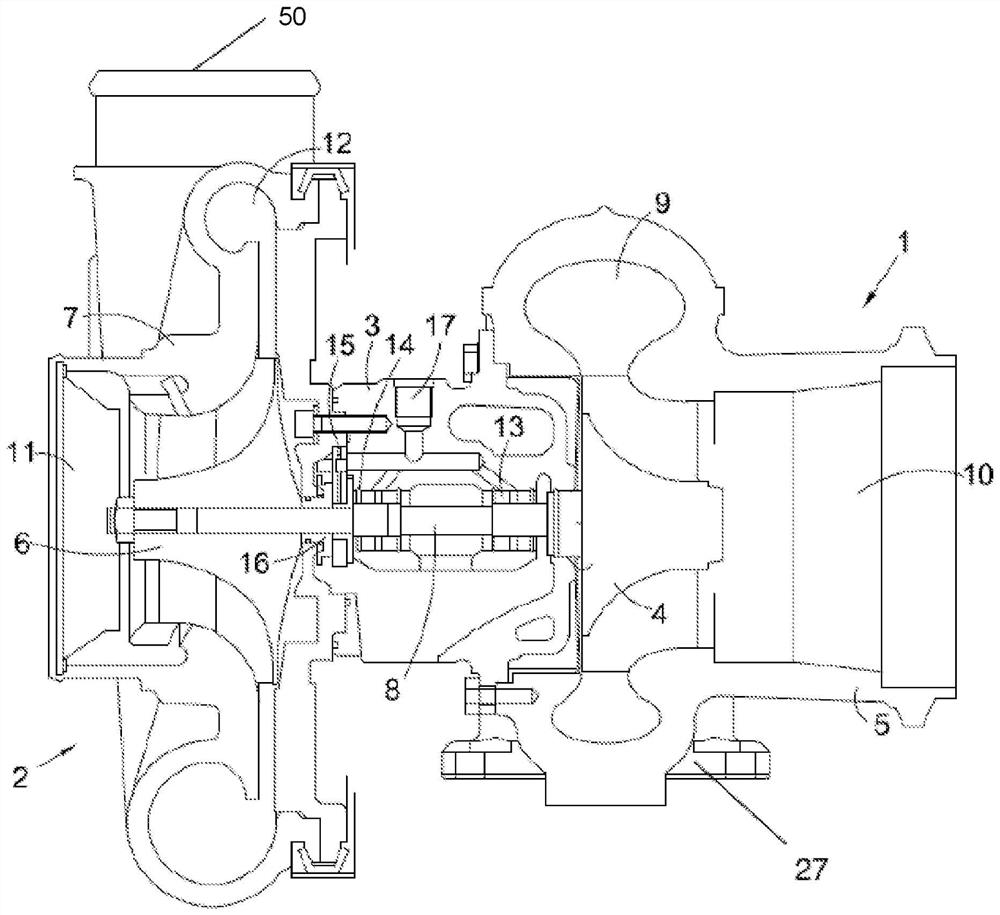
[0057] figure 1 A schematic cross-section of a known turbocharger is shown. The turbocharger comprises a turbine 1 connected to a compressor 2 via a central bearing housing 3 . The turbine 1 comprises a turbine wheel 4 for rotation in a turbine housing 5 . Similarly, the compressor 2 includes a compressor wheel 6 rotatable within a compressor housing 7 . The compressor housing 7 defines a compressor chamber within which the compressor wheel 6 is rotatable. The turbine wheel 4 and the compressor wheel 6 are mounted on opposite ends of a common turbocharger shaft 8 which extends through the central bearing housing 3 .

[0058] The turbine housing 5 has an exhaust gas inlet volute 9 positioned annularly around the turbine wheel 4 and an axial exhaust gas outlet 10 . The compressor housing 7 has an axial inlet passage 11 and a volute 12 arranged angularly around the compressor chamber. The volute 12 is in gas flow communication with a compressor outlet 50 . The turbocharger ...


PUM


Abstract

A turbine arrangement includes a turbine having a turbine housing defining a turbine chamber, a turbine inlet upstream of a turbine wheel, and a turbine outlet downstream of a turbine wheel supported for rotation within the turbine chamber. The turbine arrangement also includes a flow passage between a location upstream of the turbine wheel and a location downstream of the turbine wheel, the flow passage being configured to allow gas to flow from said location upstream of the turbine wheel to said location downstream of the turbine wheel without interfering with Turbine wheel interaction. The turbine arrangement further comprises a valve arrangement comprising: a valve member movable between an open configuration and a closed configuration, wherein in the open configuration gas can flow through the flow channel from said location upstream of the turbine wheel to downstream of the turbine wheel and in the closed configuration, gas is substantially prevented from flowing through the flow passage; a first actuator portion connectable to the actuator for moving the valve member between the open configuration and the closed configuration; and a second actuator portion in gas flow communication with a portion of the turbine device upstream of the turbine wheel via the actuator gas passage; and wherein the turbine device is configured such that gas can pass through the actuator gas passage from the turbine device upstream of the turbine wheel Said portion flows to the second actuator portion such that the pressure of said gas flowing to the second actuator portion through the actuator gas passage acts on the second actuator portion to push the valve member towards closure configuration.

Description

technical field [0001] The present invention relates to a turbomachine, and more particularly to a turbomachine having a wastegate to allow gas to bypass the turbine wheel. The turbine may form part of a turbocharger or power turbine. Background technique [0002] A turbine mechanism is a machine that transfers energy between a rotor and a fluid. For example, a turbine mechanism may transfer energy from a fluid to a rotor or may transfer energy from a rotor to a fluid. Two examples of turbo mechanisms are a power turbine, which uses the rotational energy of a rotor to do useful work (eg, generate electricity), and a turbocharger, which uses the rotational energy of a rotor to compress a fluid. [0003] A turbocharger is a well known device for supplying air to the intake port of an internal combustion engine at a pressure above atmospheric pressure (boost pressure). A conventional turbocharger basically consists of a turbine wheel driven by exhaust gases on a rotatable sh...

Claims


Application Information

Patent Timeline
Patent Type & Authority Patents(China)
IPC IPC(8): F01D17/10F02B37/02F02B37/18F02C6/12
CPCF01D17/105F02B37/18F02B37/183F02C6/12F05D2220/40Y02T10/12F02B37/186F05D2260/606
Inventor 詹姆士·亚历山大·麦克文托马斯·莫顿
Owner CUMMINS LTD
Learn More