
image forming device

An image and image carrier technology, which is applied to the electrical recording process using charge patterns, equipment and instruments of the electrical recording process applying charge patterns, etc., can solve problems such as damage, achieve good transfer efficiency, and suppress excess current. Effect

Active Publication Date: 2022-02-08
KATSURAGAWA ELECTRIC CO LTD
View PDF12 Cites 0 Cited by
  • Summary
  • Abstract
  • Description
  • Claims
  • Application Information

AI Technical Summary

Problems solved by technology

There is a problem that when the toner image is transferred to the surface of such a ceramic in contact with the intermediate transfer belt 113, the expensive intermediate transfer belt 113 may be damaged by the relatively hard and sharp corners of the ceramic.

Method used


Image

  • image forming device
  • image forming device
  • image forming device

Examples


Embodiment

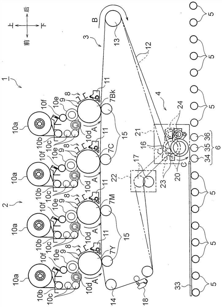
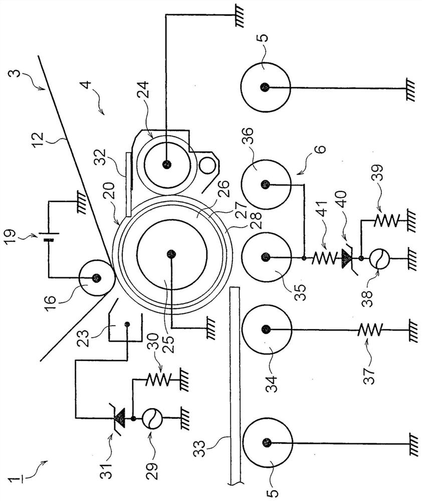
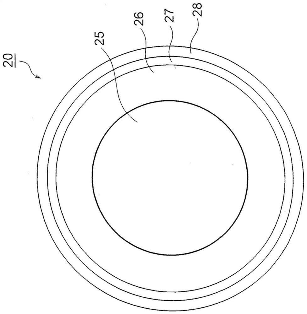
[0073] Below, refer to Figure 1 to Figure 5 Embodiments will be described.

[0074] exist figure 1 In , reference numeral 1 denotes the image forming apparatus of the present invention.

[0075] In this embodiment, the image forming apparatus 1 is a device for transferring a toner image to ceramics such as ceramics and glass (this is an example. In addition, the image forming apparatus 1 may be used to transfer a toner image to, for example, paper. printed toner image).

[0076] The image forming apparatus 1 is a color image forming apparatus of a 4-stage tandem intermediate transfer belt system, and includes an image forming unit 2 , a primary transfer unit 3 , a secondary transfer unit 4 , a conveyance unit 5 , and a third transfer unit 6 .

[0077] Next, each configuration of the image forming apparatus 1 will be described.

[0078] First, the imaging section 2 will be described.

[0079] Such as figure 1 As shown, the image forming unit 2 includes a plurality of i...


PUM


Abstract

The present invention provides an image forming apparatus in which an intermediate transfer medium is less likely to be damaged and deteriorated, and can achieve a longer life of the intermediate transfer medium. An image forming apparatus (1) structurally includes a transfer member for transferring a toner image carried on an image carrier (7Y, 7M, 7C, 7Bk) to a transfer object (33). The transfer member is configured to have an intermediate transfer belt (12) capable of rotating while being in contact with the surface of the image carrier (7Y, 7M, 7C, 7Bk) and transferred from the image carrier (7Y, 7M, 7C, 7Bk) primary transfer of the toner image; and an intermediate transfer roller (20) capable of rotating while being in contact with the surface of the intermediate transfer belt (12), which is secondarily transferred from the intermediate transfer belt (12) The toner image is transferred, and the toner image is transferred three times to the object to be transferred (33).

Description

technical field [0001] The present invention relates to an image forming apparatus that transfers toner to various transfer objects. Background technique [0002] Conventionally, as a technology of an image forming apparatus for transferring a toner image to ceramics such as ceramics and glass, for example, the technology disclosed in Patent Document 1 is known. [0003] As in Patent Document 1 figure 2 As shown, the image forming apparatus disclosed in Patent Document 1 is constituted to have: an OPC photoconductive drum 5 (image carrier) having a photoconductive layer; An electrostatic latent image is formed; a developing unit 8a (developing member) for attaching toner to the electrostatic latent image formed on the OPC photoconductive drum 5 to form a toner image; a transfer roller 7 (transfer member) ), which rotates in contact with the surface of the OPC photoconductive drum 5, is transferred (primary transfer) the toner image formed on the OPC photoconductive drum 5 ...

Claims


Application Information

Patent Timeline
Patent Type & Authority Patents(China)
IPC IPC(8): G03G15/16
CPCG03G15/16
Inventor 藏本伸也橘高英治
Owner KATSURAGAWA ELECTRIC CO LTD
Learn More