Real-time embedded equipment for animal step counting and positioning in animal husbandry
An embedded device, animal husbandry technology, applied in animal husbandry, other equipment, applications, etc., can solve the problems of high research and development costs, high power consumption, and difficult communication methods for animal sign monitoring equipment
- Summary
- Abstract
- Description
- Claims
- Application Information
AI Technical Summary
Problems solved by technology
Method used
Image
Examples
Embodiment 1
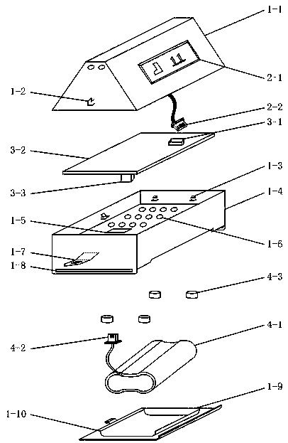
[0025] Embodiment 1: as Figure 1-2 Shown, a kind of real-time embedded equipment for animal husbandry step counting and positioning, including equipment shell, OLED display module 2-1, control circuit board 3-2 and storage battery pack 4-1, described equipment shell is from top The lower part is divided into three parts, which are the equipment top case 1-1, the equipment box body 1-4 and the battery compartment cover 1-9, wherein the OLED display module 2-1 is fixed on one side of the equipment top case 1-1; The equipment box body 1-4 is divided into two layers, the upper layer is used to fix the control circuit board 3-2, and the lower layer is used to place the battery pack 4-1; the battery compartment cover 1-9 is fixed on the bottom of the equipment box body 1-4;
[0026] The device top case 1-1 is sleeved on the device case body 1-4 through the box body connection buckle I1-2 and the box body connection buckle II1-7 on both sides, and the two sides of the device top cas...
Embodiment 2
[0029] Embodiment 2: as Figure 8As shown, the OLED display module 2-1 includes OLED screen M1, SSD1306 display driver chip U7, capacitor C17, capacitor C18, capacitor C19, capacitor C20, capacitor C21, capacitor C22, capacitor C23, capacitor C24, resistor R9, Resistor R10, resistor R11, resistor R12, 1N4148 diode D3, OLED screen control interface female 3-1. The circuit connection method is as follows: OLED screen M1 is connected to SSD1306 display driver chip U7 through a cable. Pin 1 of SSD1306 display driver chip U7 is connected to one end of capacitor C17, and the other end of capacitor C17 is connected to pin 2 of SSD1306 display driver chip U7. Pin 3 of SSD1306 display driver chip U7 is connected to one end of capacitor C18, and the other end of capacitor C18 is connected to pin 4 of SSD1306 display driver chip U7. Pin 5 and pin 8 of SSD1306 display driver chip U7 are simultaneously connected to the positive pole of the 3V3 power supply; the positive pole of the 3V3 p...
Embodiment 3
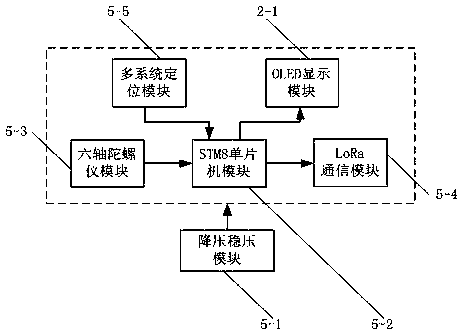
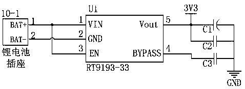
[0030] Embodiment 3: The control circuit board 3-2 includes several circuit modules, including a step-down regulator module 5-1, an STM8 single-chip microcomputer module 5-2, a six-axis gyroscope module 5-3, a LoRa communication module 5-4, Multi-system positioning module 5-5. The step-down regulator module 5-1 uses the RT9193-33 ultra-low dropout fast linear regulator, which has extremely low noise and quiescent current consumption, and is small in size. It is a linear regulator specially launched for wireless radio frequency , the maximum current is 300mA, only consumes 0.01uA current in shutdown mode, and the start-up time is 50us, which is very suitable for equipment that often starts and stops. The STM8 single-chip microcomputer module 5-2 uses the STM8S003F3 model processor produced by ST Company, with a main frequency of 16MHz, an 8-bit MCU, small size and low power consumption. The six-axis gyroscope module 5-3 uses the MPU6050 chip, which integrates a 3-axis MEMS gyr...
PUM
 Abstract
Description
Claims
Application Information
 - R&D
- Intellectual Property
- Life Sciences
- Materials
- Tech Scout
- Unparalleled Data Quality
- Higher Quality Content
- 60% Fewer Hallucinations
Browse by: Latest US Patents, China's latest patents, Technical Efficacy Thesaurus, Application Domain, Technology Topic, Popular Technical Reports.
© 2025 PatSnap. All rights reserved.Legal|Privacy policy|Modern Slavery Act Transparency Statement|Sitemap|About US| Contact US: help@patsnap.com


