
A method for increasing imaging depth range of sweep frequency optical coherence tomography system

An optical coherence tomography and imaging system technology is applied in the field of increasing the imaging depth range of a swept-frequency optical coherence tomography system, and can solve the problems of increasing data processing complexity, increasing system cost and complexity, and reducing costs and complexity. The effect of stability, ease of implementation, and simple system structure

Inactive Publication Date: 2019-01-08
SHANGHAI INST OF OPTICS & FINE MECHANICS CHINESE ACAD OF SCI
View PDF2 Cites 12 Cited by
  • Summary
  • Abstract
  • Description
  • Claims
  • Application Information

AI Technical Summary

Problems solved by technology

[0009] All of the above methods can increase the imaging depth range of the system, but they all need to add additional devices, such as acousto-optic modulators, multiple reference arms, and change the design of the sample arm, etc., which increase the cost and complexity of the system
In addition, some methods will increase the complexity of data processing

Method used


Image

  • A method for increasing imaging depth range of sweep frequency optical coherence tomography system
  • A method for increasing imaging depth range of sweep frequency optical coherence tomography system
  • A method for increasing imaging depth range of sweep frequency optical coherence tomography system

Examples


Embodiment Construction

[0041] The present invention will be further described below in conjunction with the examples and drawings, but the examples should not limit the protection scope of the present invention.

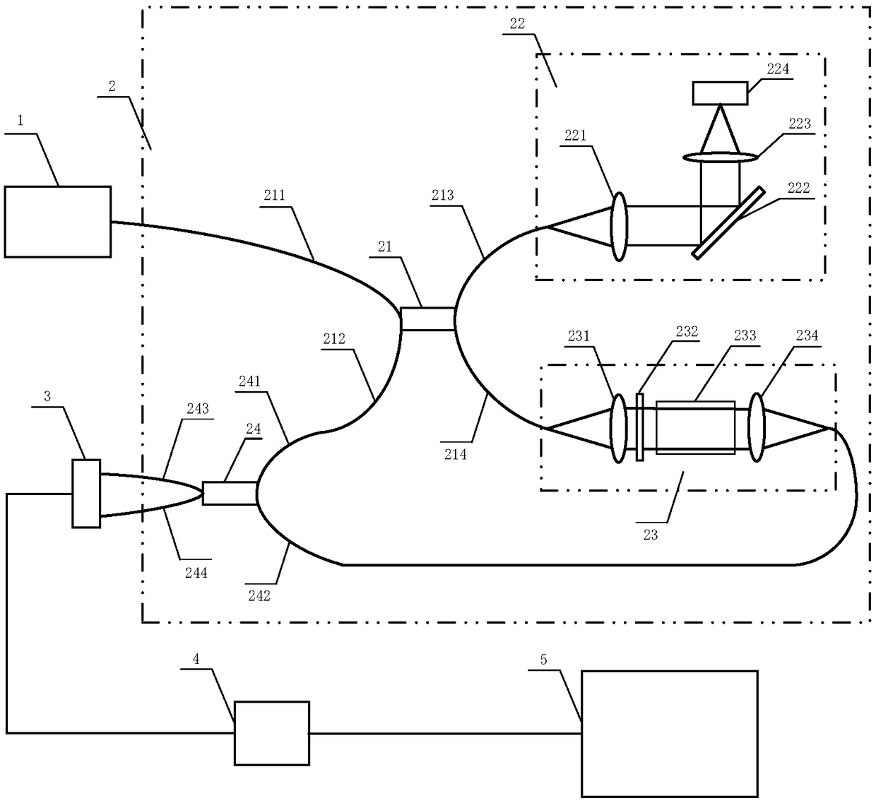
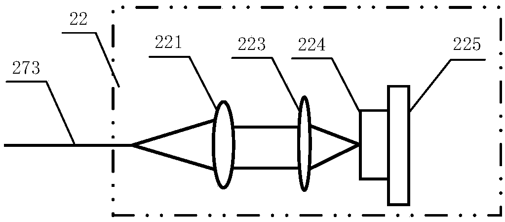
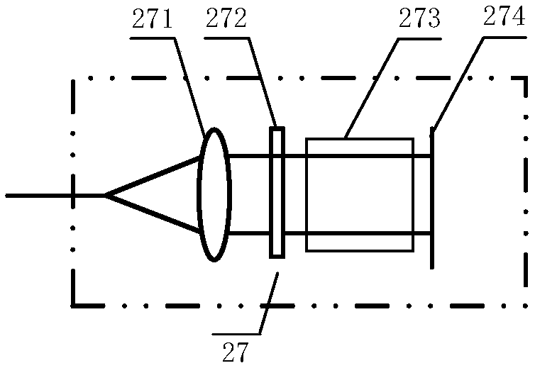
[0042] see figure 1 , figure 1 It is a structural schematic diagram of the fiber-optic frequency-swept optical coherence tomography system of the present invention. It includes a frequency-sweeping light source 1, the output port of the frequency-sweeping light source 1 is connected to the first port 211 of the first coupler 21, the second port 212 is connected to the first port 241 of the second coupler 24, and the first coupler 21 will The light is divided into two paths 213 and 214, which are respectively connected to the sample light path 22 and the reference light path 23. In the sample optical path 22, the third port 213 of the first coupler 21 is connected to the first collimating lens 221, and the two-dimensional scanning galvanometer 222, the focusing lens 223 and the sample to ...


PUM

PropertyMeasurementUnit
thicknessaaaaaaaaaa
thicknessaaaaaaaaaa

Abstract

The invention discloses a method for increasing an imaging depth range of a sweep optical coherence tomography system. In this method, the system interference signals with equal time intervals are collected at high speed, and the system interference signals with equal time intervals are calibrated as the system interference signals with equal wavenumber intervals to increase the imaging depth range of the system. The higher the rate of high-speed acquisition, the more sampling points in a spectral range, and the greater the imaging depth range of the system. In data processing, the interference signal with constant optical path difference is used to demarcate the system interference signal with equal intervals in high-speed acquisition as the system interference signal with equal intervalsin wavenumber. The realization mode of the invention is simple in structure, easy to operate, and reduces the system cost and complexity.

Description

technical field [0001] The invention relates to frequency-domain optical coherence tomography (Fourier Domain Optical Coherence Tomography, FDOCT for short), in particular to a method for increasing the imaging depth range of a frequency-sweeping optical coherence tomography system. Background technique [0002] At present, more and more people are affected by eye diseases, such as hyperopia, glaucoma, age-related macular degeneration and diabetic retinopathy, etc., and the early symptoms of these eye diseases are mainly reflected in changes in eye structure and shape. Therefore, it is of great significance to obtain high-resolution whole-eye information, such as cornea, lens and retinal thickness and eye axial length, for the diagnosis of ophthalmic diseases. [0003] Optical coherence tomography (OCT for short) is a biomedical optical imaging technique that obtains structural information at different depths of a sample by detecting the intensity of backscattered light from...

Claims


Application Information

Patent Timeline
Patent Type & Authority Applications(China)
IPC IPC(8): A61B3/10G01N21/84
CPCA61B3/102G01N21/84
Inventor 王瑄李中梁王向朝南楠步扬曾爱军
Owner SHANGHAI INST OF OPTICS & FINE MECHANICS CHINESE ACAD OF SCI
Learn More