Dry particle mixing device

A mixing device, dry particle technology, applied in mixers, mixing methods, solid and solid mixing, etc., can solve problems such as poor mixing effect

Pending Publication Date: 2019-01-08
UNIV OF SCI & TECH LIAONING
View PDF7 Cites 11 Cited by
  • Summary
  • Abstract
  • Description
  • Claims
  • Application Information

AI Technical Summary

Problems solved by technology

[0003] At present, the commonly used dry particle mixing device adopts a mixing chamber structure, that is, a stirring device is installed in the mixing chamber. The stirring device is composed of a plurality of stirring blades, and most of the stirring blades are smooth blades. Although the stirring resistance is small, the mixing effect is better. Difference

Method used


Image

  • Dry particle mixing device
  • Dry particle mixing device
  • Dry particle mixing device

Examples


Embodiment Construction

[0026] The specific embodiment of the present invention will be further described below in conjunction with accompanying drawing:

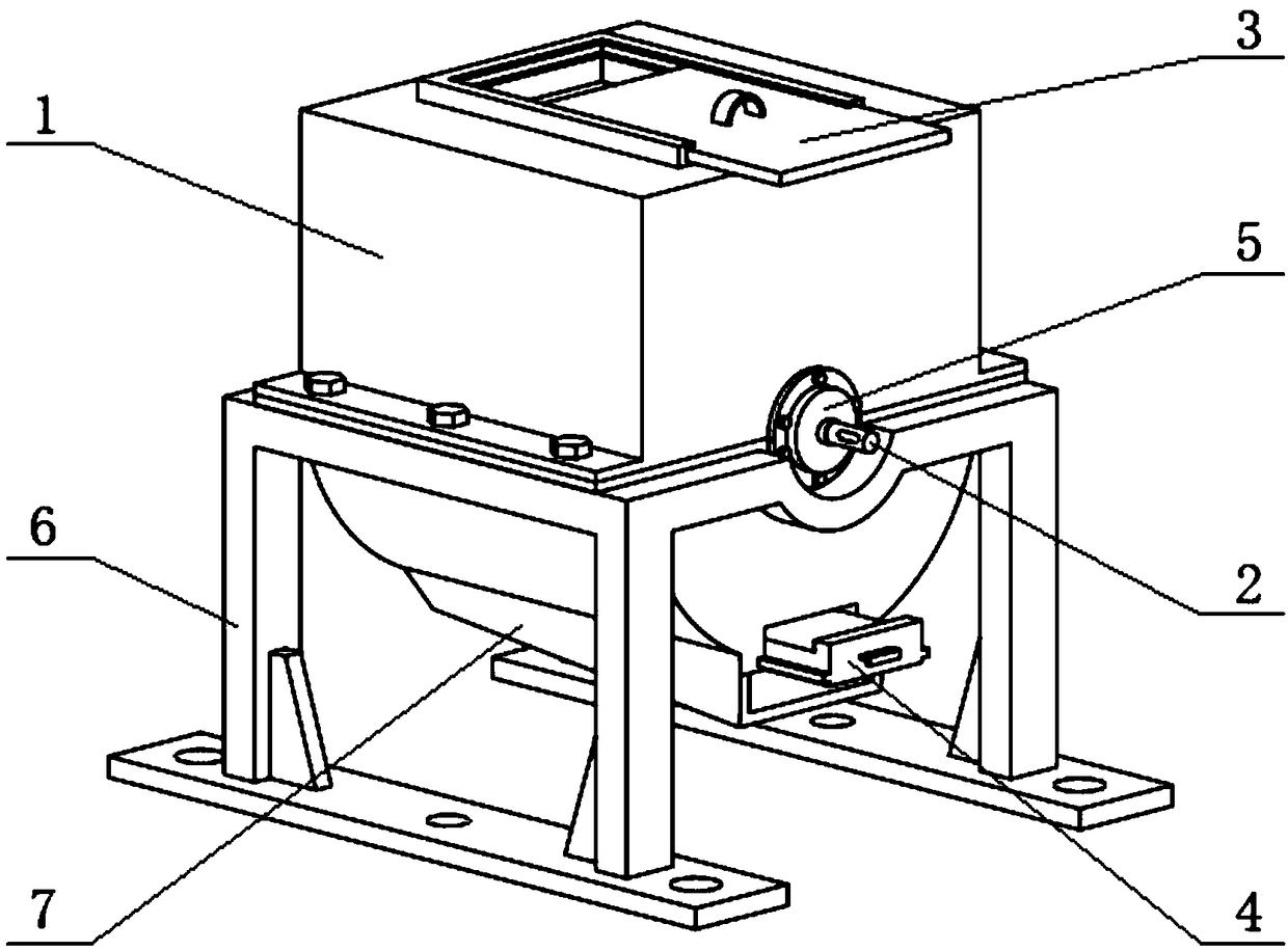
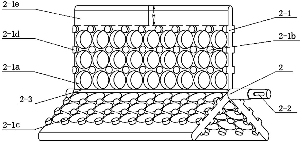
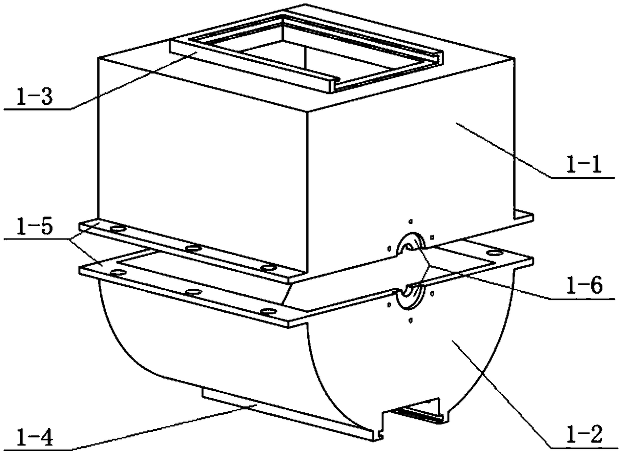
[0027] like figure 1 , figure 2 As shown, a dry particle mixing device of the present invention includes a mixing chamber 1 and an agitator located in the mixing chamber 1; the agitator is composed of an agitating shaft 2 and at least three agitating blades 2-1; the agitating blade 2-1 is provided with a fan-shaped rib 2-3 at the junction of the stirring shaft 2, and the area near the outer edge of each stirring blade 2-1 is the bare plate area 2-1e, and the stirring blade 2-1 outside the light plate area 2-1e There are a plurality of mixing holes along the horizontal and vertical directions, and a plurality of mixing protrusions are distributed on the stirring blade outside the bare plate area 2-1e at the same time, and the mixing holes and mixing protrusions are regular on the stirring blade 2-1 distributed.

[0028] The mixing hole is one o...


PUM


Abstract

The invention relates to a dry particle mixing device which comprises a mixing bin and a stirrer disposed in the mixing bin, wherein the stirrer comprises a stirring shaft and at least three stirringblades; fan-shaped ribs are disposed at joints between the stirring blades and the stirring shaft; an area of each of the stirring blades closed to the outer edge is a light plate area; a plurality ofmaterial mixing holes are formed in the stirring blades outside the light plate area in the lateral direction and the longitudinal direction; a plurality of material mixing bulges are simultaneouslydistributed on the stirring blades outside the light plate area; and the material mixing holes and the material mixing bulges are regularly distributed on the stirring blades. According to the deviceprovided by the invention, the light plate areas on the stirring blades are utilized to drive all particles to move, so that the particles flow on the stirring blades, and diverging flows and converging flows are generated continuously after the particles contact with the material mixing holes and the material mixing bulges; and the material mixing bulges can also change the original motion directions of the particles, so that the movement directions of the particles are more irregular, the particulate matter is loose, and finally the desired mixing uniformity is achieved.

Description

technical field [0001] The invention relates to the technical field of dry granule mixing, in particular to a dry granule mixing device suitable for powder or granular materials in chemical industry, food, medicine, feed, ceramics, metallurgy and other industries. Background technique [0002] Mixing refers to the operation process in which two or more materials with different components change their movement speed and direction under the action of external force (gravity and mechanical force), so that the particles of each component can be evenly distributed. This operation process is also called homogenization process. The material obtained after mixing operation is called mixture. It is customary to call the movement between the same phases mixing, the movement between different phases is called stirring, and the operation of mixing high-viscosity liquids and solids is called kneading or kneading. This operation is equivalent to the intermediate degree of mixing and stir...

Claims


Application Information

Patent Timeline
Patent Type & Authority Applications(China)
IPC IPC(8): B01F7/04B01F15/00B01F15/02B01F3/18
CPCB01F23/60B01F27/11251B01F27/191B01F27/70B01F35/45B01F35/51B01F35/43B01F35/71B01F35/75
Inventor 李玲玲刘正海郭柄江赵磊于海川陈广慧丁贺贺王泊涵马学东
Owner UNIV OF SCI & TECH LIAONING
Why Eureka
Try Eureka