Large crankshaft mold with coupling bionic surface

A mold and crankshaft technology, which is applied in the field of large crankshaft die forging molds, can solve the problems that the service life of the mold cannot be significantly improved, and achieve the effects of easy automatic production, reduction of residual stress, and convenient and flexible processing

Active Publication Date: 2019-01-08
JILIN UNIV
View PDF7 Cites 5 Cited by
  • Summary
  • Abstract
  • Description
  • Claims
  • Application Information

AI Technical Summary

Problems solved by technology

Therefore, the current treatment method cannot s

Method used


Image

  • Large crankshaft mold with coupling bionic surface
  • Large crankshaft mold with coupling bionic surface
  • Large crankshaft mold with coupling bionic surface

Examples


Embodiment example

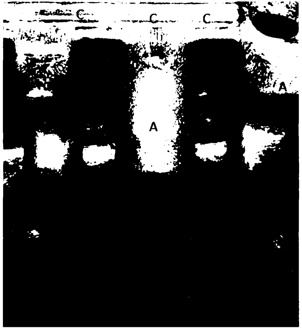
[0026] Such as figure 1 As shown, with reference to the wear condition of the scrapped large crankshaft mold, the present invention adopts a block strengthening method according to the wear appearance and furrow depth combined with the computer finite element analysis results of the force on the mold surface. The working surface of the large crankshaft mold is divided into three regions according to the force, damage mode and wear morphology. The convex part of the mold cavity with wear patterns such as furrows on the working surface is area A, the concave part of the cavity with less wear but more thermal fatigue lines is area B, and the upper and lower molds with fatigue lines and shallow furrows The contact surface of mold clamping is area C; different coupling bionic models are prepared in the three areas.

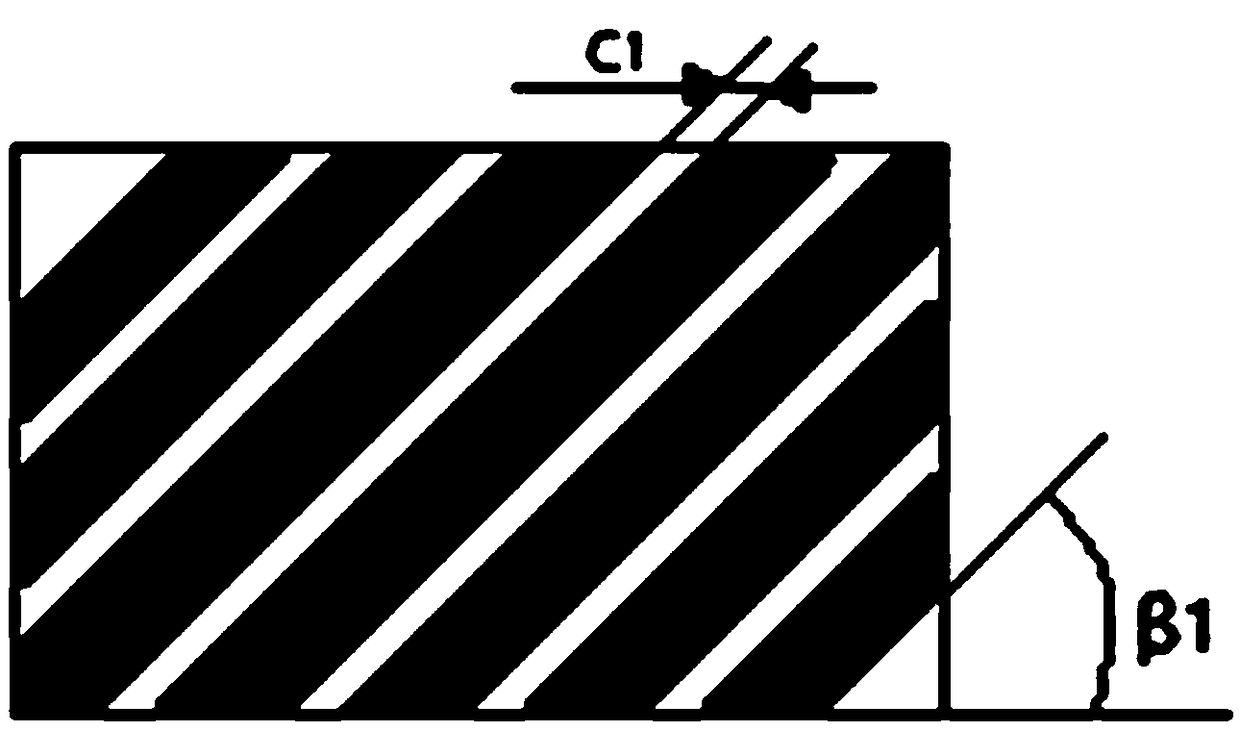
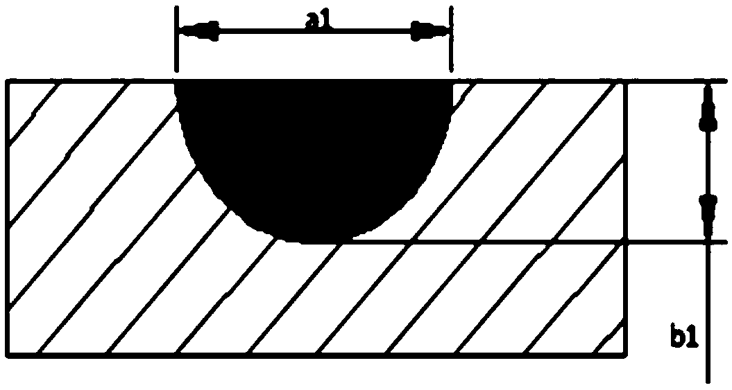
[0027] Aiming at the working surface of area A with greater wear, a unit body model with densely packed thick stripes was prepared. Such as Figure 2a , Figure 2b...


PUM

PropertyMeasurementUnit
Widthaaaaaaaaaa
Average sizeaaaaaaaaaa
Defocus amountaaaaaaaaaa

Abstract

The invention relates to a large crankshaft mold with a coupling bionic surface. Referring to the abrasion condition of a scrapped mold and according to differences of the stress size, the damage modeand the abrasion morphology, the working surface of the mold is divided into three zones; a convex part in a mold cavity is a zone A, a concave part of the mold cavity is a zone B, and a contact surface of an upper mold and a lower mold after being closed is a zone C; the zone A is used for preparing a dense-arranged heavy stripe unit body model to retard the abrasion effectively; the zone B is used for preparing a sparse-arranged thin stripe unit body model to hinder the development of fatigue cracks effectively, and to retard the abrasion; and the zone C is used for preparing a uniformly-arranged latticed unit body model so as to enhance the strength of an arc transition joint of the mold, and to retard the abrasion effectively. According to the large crankshaft mold with the coupling bionic surface, the hardness, wear resistance and the thermal-crack-development-resistance performance of the working surface of the mold can be remarkably improved.

Description

technical field [0001] The invention belongs to the technical field of metal material surface strengthening, and relates to a large crankshaft die forging die with coupled bionic surface strengthening. Background technique [0002] During the forging process of a large crankshaft, the mold needs to withstand huge impact pressure. The surface shape of the mold cavity is complex and the depth is different, so that the force on the surface of each cavity is uneven. When the hot metal enters the mold cavity, the surface of the mold cavity heats up rapidly, which is equivalent to tempering treatment, and the flowing billet will scour, squeeze and rub the mold cavity, softening the mold and increasing wear. In this process, not only the surface roughness of the mold is destroyed, resulting in deviation of the forging, but also groove marks on the surface of the mold. In addition, during the repeated forging process, the mold is subjected to cyclic thermal stress and wear, which ...

Claims


Application Information

Patent Timeline
IPC IPC(8): B21J13/02B21K1/08
CPCB21J13/02B21K1/08
Inventor 支本丰周宏李静平周倜张凯迅
Owner JILIN UNIV
Why Eureka
Try Eureka