A high-precision and fast positioning device based on the principle of end gear positioning

A technology of positioning device and end tooth disc, applied in positioning devices, chucks, manufacturing tools, etc., can solve the problems of extremely high dimensional accuracy and topographic accuracy, and achieve good repeatability of positioning accuracy, good automatic centering, and accurate maintenance. long life effect

Active Publication Date: 2021-03-23
HARBIN INST OF TECH
View PDF8 Cites 0 Cited by
  • Summary
  • Abstract
  • Description
  • Claims
  • Application Information

AI Technical Summary

Problems solved by technology

However, due to the extremely high requirements for dimensional accuracy and shape accuracy in the ultra-precision field, the current quick clamping and positioning system can no longer meet this requirement.

Method used


Image

  • A high-precision and fast positioning device based on the principle of end gear positioning
  • A high-precision and fast positioning device based on the principle of end gear positioning
  • A high-precision and fast positioning device based on the principle of end gear positioning

Examples


specific Embodiment approach 1

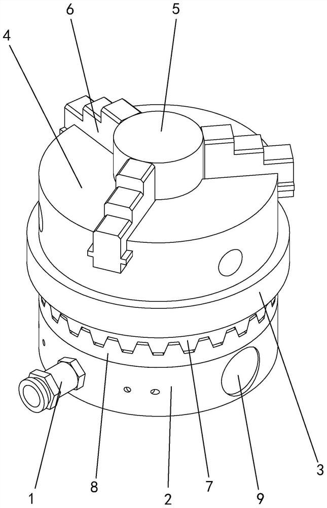
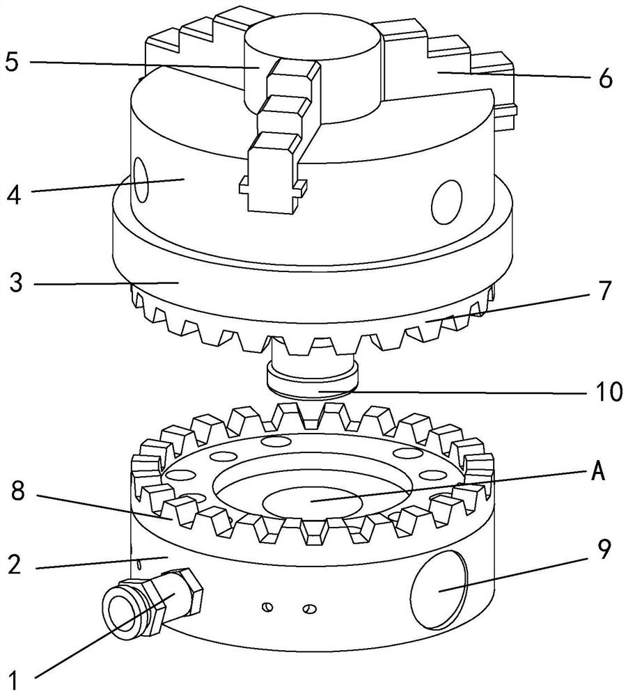
[0015] Specific implementation mode one: as Figure 1 to Figure 8 As shown, the present invention discloses a high-precision rapid positioning device based on the positioning principle of the end tooth disc, including an air joint 1, a columnar base 2, a base plate 3, a three-jaw chuck 4, a joint 10, an end tooth disc and a clamping mechanism, the columnar base 2 is vertically arranged and the middle part of the upper surface is provided with a circular groove A, and the outer peripheral surface of the columnar base 2 is provided with a through hole B and a circular groove C, and the through hole B is connected with the circular groove Groove 1A and round groove 2C are connected to each other, and a clamping mechanism is placed in through hole 1B. The round groove 2C is detachably connected to one end of the gas connector 1 through threads, and the other end of the gas connector 1 Coupled with the high-pressure gas source end joint, the high-pressure gas enters the interior of...

specific Embodiment approach 2

[0016] Specific implementation mode two: as figure 1 , 2 , 4, and 6, this embodiment is a further description of specific embodiment 1, the through hole 1 B and the circular groove 2 C are arranged along the radial direction of the columnar base 2, and the through hole 1 B and the circular groove 2 Groove two C are arranged perpendicular to each other.

specific Embodiment approach 3

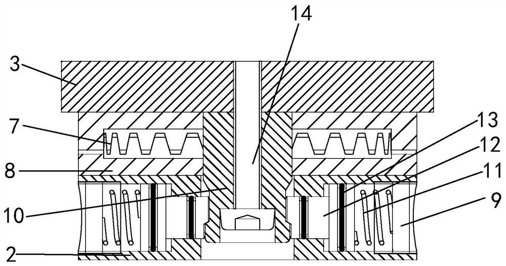
[0017] Specific implementation mode three: as Figure 4 As shown, this embodiment is a further description of Embodiment 1 or Embodiment 2. The circular groove 2C communicates with the through hole 1B through the air channel G provided inside the columnar base 2 .


PUM


Abstract

The invention discloses a high-precision quick positioning device based on an end tooth disc positioning principle, and relates to a positioning device. A columnar base is vertically arranged, and isprovided with a first round groove at the middle part of the upper surface; a first through hole and a second round groove are formed in the outer peripheral surface; the first through hole communicates with the first round groove and the second round groove; a clamping mechanism is arranged in the first through hole; the second round groove is connected with one end of an air joint; an end toothdisc is connected with the columnar base and a substrate; a third through hole communicating with the first through hole is formed in the middle part of the upper surface of the end tooth disc; the lower end of the joint penetrates through the third through hole in a gap mode, and is placed in the first round groove; the lower end of the joint is clamped through the clamping mechanism; the upper end of the joint is fixedly connected with the substrate; and the upper end of the substrate is detachably connected with the lower end of a three-jaw chuck. Compared with a traditional structure, thedevice is simpler in structure and suitable for the positioning, clamping and transposition process in the machining process of ultra-precise parts, reduces 80% of the stop time of a machine tool, improves the working efficiency by 2-3 times, and can reduce the transposition operation error below 0.001 mm in the machining process.

Description

technical field [0001] The invention relates to a positioning device, in particular to a high-precision and rapid positioning device based on the positioning principle of an end tooth disc, which belongs to a new type of machine tool fixture. Background technique [0002] The quick positioning device is a unique positioning and locking device, which can reduce the error caused by the clamping process as much as possible. Its advantages of high efficiency and convenience make it not only used in ordinary machining, but also in the field of ultra-precision. Most parts in the ultra-precision field are produced in small batches, especially customized parts. For some parts, they need to be frequently disassembled to special testing equipment for size and shape inspection during the processing process. If the error between the two parts is well controlled, the final machining accuracy cannot be guaranteed. Therefore, it is necessary to use the same set of rapid positioning syste...

Claims


Application Information

Patent Timeline
Patent Type & Authority Patents(China)
IPC IPC(8): B23Q3/06B23B31/10
CPCB23B31/10B23Q3/06
Inventor 孙涛王哲赵学森
Owner HARBIN INST OF TECH
Why Eureka
Try Eureka