
Display panel, method for forming the same, and display

A technology for display panels and substrates, which is applied to electrical components, electrical solid-state devices, circuits, etc., and can solve the problems that OLED display devices cannot display normally.

Active Publication Date: 2019-01-08
YUNGU GUAN TECH CO LTD
View PDF6 Cites 14 Cited by
  • Summary
  • Abstract
  • Description
  • Claims
  • Application Information

AI Technical Summary

Problems solved by technology

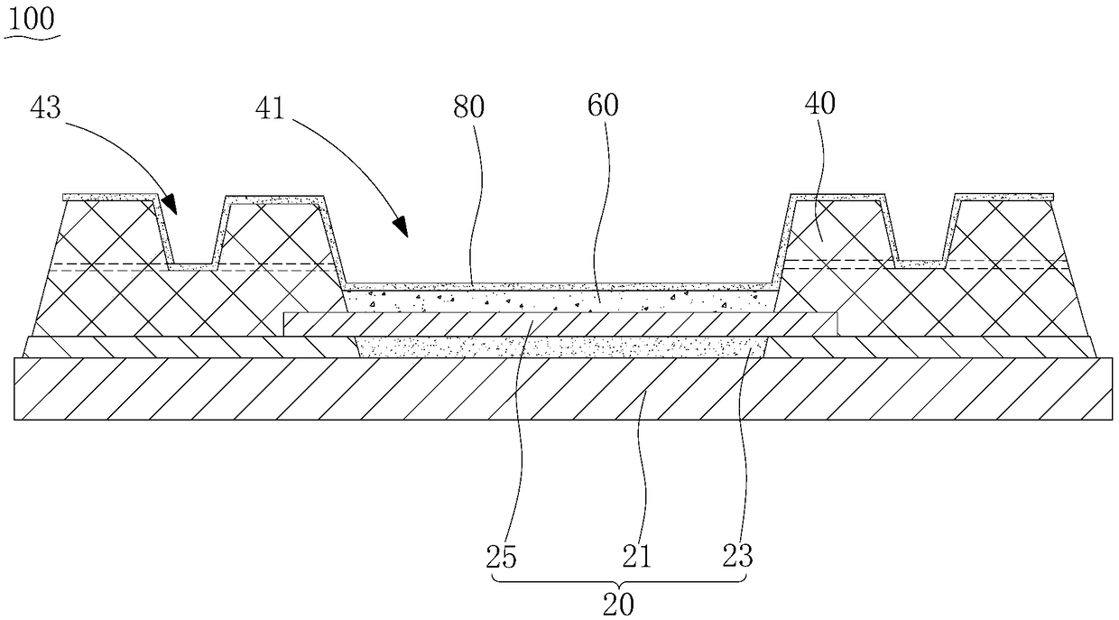
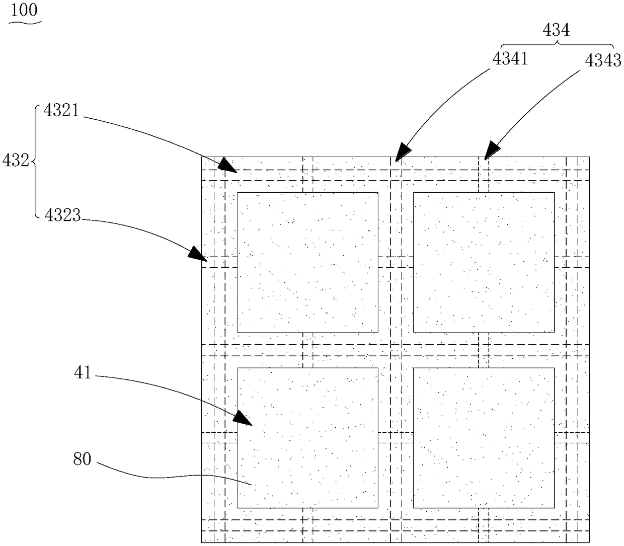
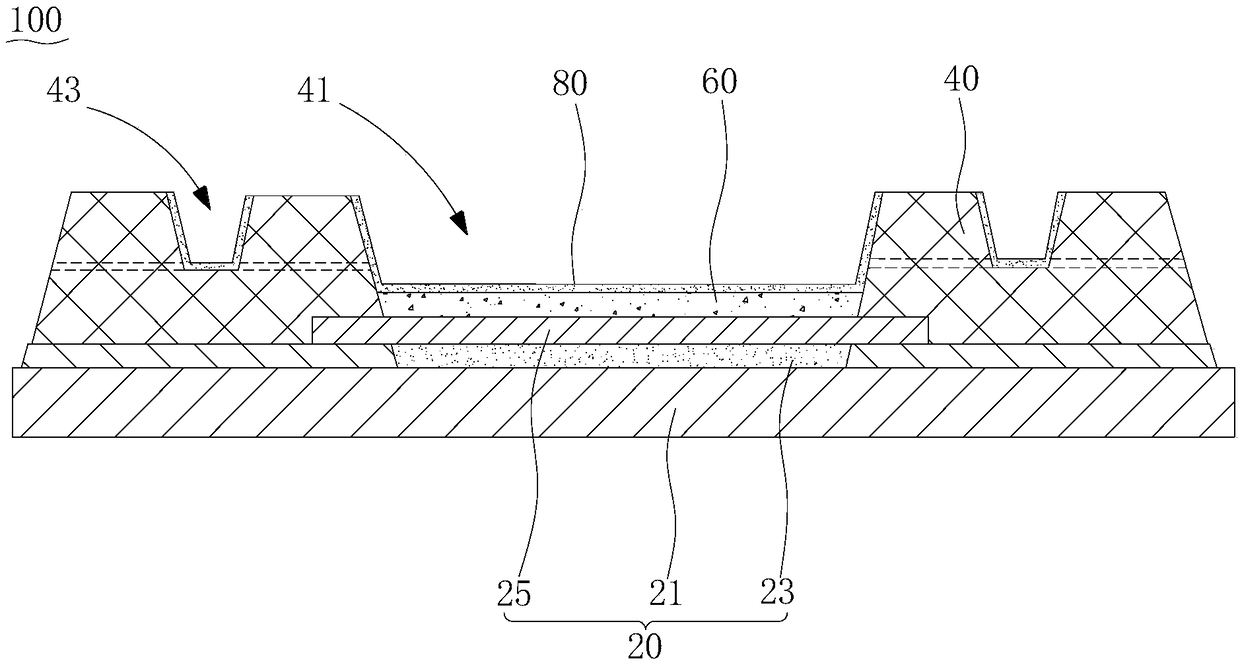
[0004] Based on this, it is necessary to address the problem that OLED display devices cannot display normally when they are impacted by external forces, and provide a display panel, a forming method, and a display device that improve the above problems.

Method used


Image

  • Display panel, method for forming the same, and display
  • Display panel, method for forming the same, and display
  • Display panel, method for forming the same, and display

Examples


Embodiment Construction

[0035] In order to facilitate the understanding of the present invention, the present invention will be described more fully below with reference to the associated drawings. Preferred embodiments of the invention are shown in the accompanying drawings. However, the present invention can be embodied in many different forms and is not limited to the embodiments described herein. On the contrary, these embodiments are provided to make the understanding of the disclosure of the present invention more thorough and comprehensive.

[0036] It should be noted that when an element is referred to as being “fixed” to another element, it can be directly on the other element or there can also be an intervening element. When an element is referred to as being "connected to" another element, it can be directly connected to the other element or intervening elements may also be present. The terms "vertical," "horizontal," "left," "right," and similar expressions are used herein for purposes ...


PUM


Abstract

The invention relates to a display panel and a forming method thereof. A pixel definition layer formed on the array substrate, wherein the pixel definition layer defines a plurality of pixel definition openings; A light emit layer is for in an opening defined by a pixel; A cathode layer covering a pixel definition layer and a light emitting layer; The display panel further includes a recess formedon the side of the pixel definition layer facing away from the array substrate, and a cathode layer covering the recess is electrically connected with the cathode layer covering each of the light emitting layers to form a cathode circuit. The above display panel, As that external force act on the pixel definition layer, As that cathode lay covering the concave portion can form a complete cathodeloop with the cathode lay covering each light-emitting layer, the cathode loop is still conductive when a part of the cathode layer is damaged, and the display panel can still display normally. The surface of the pixel definition lay on the side of the array substrate away from which the concave portion is not formed is first subjected to an external force.

Description

technical field [0001] The present invention relates to the field of display devices, in particular to a display panel, a forming method thereof, and a display device. Background technique [0002] In recent years, with the development of society and the advancement of science and technology, the technological development of smart terminal equipment and wearable equipment is changing rapidly, and the requirements for flat panel display are gradually increasing, and the demand is becoming more and more diverse. OLED (Organic Light-Emitting Diode, Organic Light-Emitting Diode) display device has lower power consumption compared with liquid crystal display, and at the same time has higher brightness and response speed, and can be bent and has good flexibility, so it is more and more used. It is more widely used in smart terminal products such as mobile phones, tablet computers and even TVs, and has become the mainstream display in the display field. [0003] However, due to ma...

Claims


Application Information

Patent Timeline
Patent Type & Authority Applications(China)
IPC IPC(8): H01L27/32H01L51/52H01L51/56
CPCH10K59/122H10K50/82H10K71/00
Inventor 朱平李雪原刘胜芳黄莹
Owner YUNGU GUAN TECH CO LTD
Learn More