A patterned honeycomb cell broadband periodic microwave absorbing structure

A honeycomb structure and wave structure technology, applied in electrical components, antennas, etc., can solve problems such as insufficient absorption bandwidth, and achieve the effect of completely consistent absorption performance

Active Publication Date: 2019-01-08
UNIV OF ELECTRONIC SCI & TECH OF CHINA
View PDF6 Cites 16 Cited by
  • Summary
  • Abstract
  • Description
  • Claims
  • Application Information

AI Technical Summary

Problems solved by technology

[0006] In view of the above-mentioned problems or deficiencies, in order to solve the problem of insufficient absorption bandwidth of the existing absorbing structure while ensuring the structural thickness and mechanical strengt

Method used


Image

  • A patterned honeycomb cell broadband periodic microwave absorbing structure
  • A patterned honeycomb cell broadband periodic microwave absorbing structure
  • A patterned honeycomb cell broadband periodic microwave absorbing structure

Examples


Embodiment 1

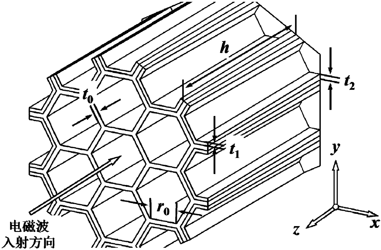
[0020] Graphical honeycomb unit broadband periodic absorbing structure, its specific size parameter is (unit: mm): r 0 =2.63,t 0 =0.2,t 1 =0.1,t 2 = 0.2, h = 23.8.

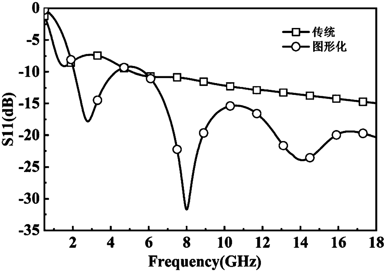
[0021] The electromagnetic absorber obtained by design is insensitive to the incident azimuth angle in the case of a uniform plane wave vertical incidence, and the omni-directional absorption performance is completely consistent. In the whole frequency band of 1.5~18GHz, it has a reflection coefficient of at least -5dB, among which the frequency band of 2.05~6.85GHz has a reflection coefficient of below -10dB, the frequency band of 6.85~12.7GHz has a reflection coefficient of below -15dB, and the frequency band of 12.7~18GHz has a reflection coefficient of -20dB The following reflection coefficients, such as Figure 4 shown.

[0022] image 3 For the comparison of the absorbing efficiency of the traditional honeycomb absorbing structure when the uniform plane wave is vertically incident in this embodiment; ...

Embodiment 2

[0024] Graphical honeycomb unit broadband periodic absorbing structure, its specific size parameter is (unit: mm): r 0 =3.18,t 0 =0.2,t 1 =0.1,t 2 = 0.2, h = 23.8.

[0025] The electromagnetic absorber obtained by design is insensitive to the incident azimuth angle in the case of a uniform plane wave vertical incidence, and the omni-directional absorption performance is completely consistent. It has a reflection coefficient of at least -5dB or less in the entire frequency band of 1.71-18GHz, of which the reflection coefficient of the 2.28-7.15GHz frequency band is -10dB or less, the 7.15-13GHz frequency band has a reflection coefficient of -15dB or less, and the 13-18GHz frequency band has a reflection coefficient of -20dB or less reflection coefficient.

Embodiment 3

[0027] Graphical honeycomb unit broadband periodic absorbing structure, its specific size parameter is (unit: mm): r 0 =2.63,t 0 =0.2,t 1 =0.2,t 2 = 0.2, h = 23.8.

[0028] The electromagnetic absorber obtained by design is insensitive to the incident azimuth angle in the case of a uniform plane wave vertical incidence, and the omni-directional absorption performance is completely consistent. It has a reflection coefficient of at least -5dB or less in the entire frequency band of 1.3-18GHz, among which the reflection coefficient of the 1.57-5.6GHz frequency band is -8.5dB or less, the reflection coefficient of the 5.6-11.5GHz frequency band is -10dB or less, and the 11.5-18GHz frequency band has a reflection coefficient of - Reflection coefficient below 15dB.


PUM

PropertyMeasurementUnit
Reflection coefficientaaaaaaaaaa

Abstract

The invention belongs to the technical field of electronic materials, in particular to an electromagnetic wave absorbing structure and a design method thereof. The invention selectively impregnates the fully cured honeycomb pore microwave absorbing slurry, the maximum channel radius of the conductive channel is not only enlarged, so as to avoid the generation of high-order resonant mode in the conductive channel, increase the propagation of the incident wave in the honeycomb hole, improve the resonant absorption of the energy of the incident wave by the structure, greatly enhance the absorption performance of the low frequency, and further reduce the absorption performance of the high frequency; Compared with the traditional honeycomb absorbing structure, the pattern honeycomb absorbing structure has the same absorbing strength and the weight is lighter, and the bandwidth is 2 - 18GHz.

Description

technical field [0001] The invention belongs to the technical field of electronic materials, in particular to an electromagnetic wave-absorbing structure and a design method thereof. Background technique [0002] During World War II, the application of radar technology brought significant changes to the course of the war. Subsequently, in order to enhance the penetration performance of weapons and equipment, radar stealth technology also came into being. In the modern battlefield environment, electromagnetic radiation is becoming more and more complex. As an effective means to improve the stealth ability of weapons and equipment, electromagnetic wave-absorbing structures have also attracted more and more attention from various military powers, and relevant research results have also been frequently seen in major military and technology media. [0003] In addition, with the rapid popularization of smart phones and 4G mobile communications and the construction of super WiFi ...

Claims


Application Information

Patent Timeline
IPC IPC(8): H01Q17/00
CPCH01Q17/008
Inventor 周佩珩张国瑞任鑫王睿陈海燕邓龙江
Owner UNIV OF ELECTRONIC SCI & TECH OF CHINA
Why Eureka
Try Eureka