Supercharge Your Innovation With Domain-Expert AI Agents!

A method and system for assessing the risk of simultaneous commutation failure of multiple DC circuits

A DC system, commutation failure technology, applied in the direction of power transmission AC network, etc., can solve the problems of long time consumption and large amount of calculation

Active Publication Date: 2020-09-08
CHINA ELECTRIC POWER RES INST +4
View PDF4 Cites 0 Cited by
  • Summary
  • Abstract
  • Description
  • Claims
  • Application Information

AI Technical Summary

Problems solved by technology

[0006] In order to solve the technical problem of large amount of calculation and time-consuming method for evaluating the commutation failure risk of the DC system caused by the AC fault of the receiving end system in the prior art, the present invention provides a method for evaluating the risk of simultaneous commutation failure of multiple DC circuits method, said method comprising:

Method used


Image

  • A method and system for assessing the risk of simultaneous commutation failure of multiple DC circuits
  • A method and system for assessing the risk of simultaneous commutation failure of multiple DC circuits
  • A method and system for assessing the risk of simultaneous commutation failure of multiple DC circuits

Examples


Embodiment 1

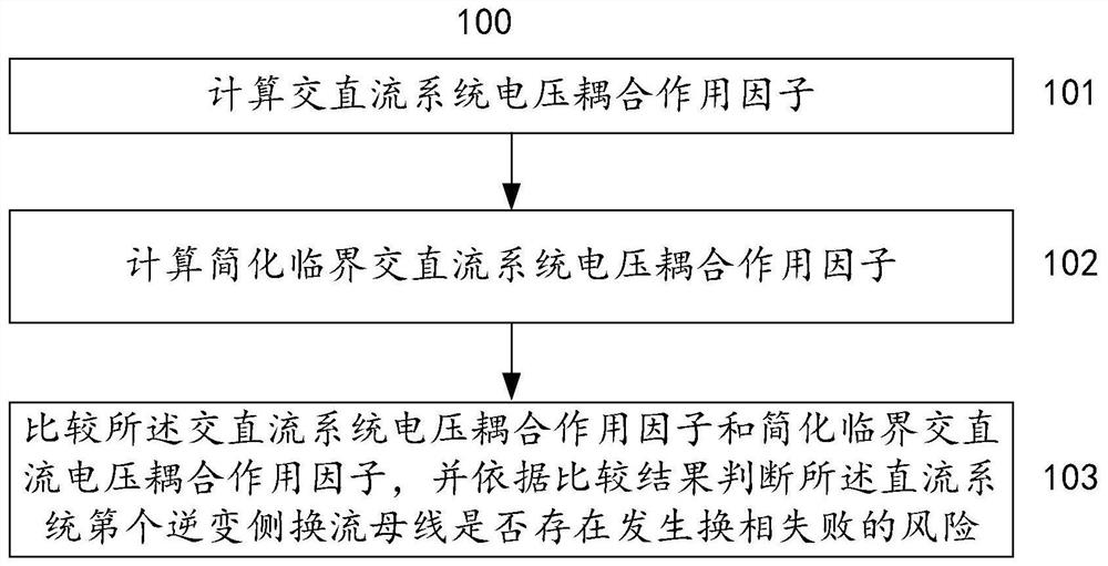
[0045] figure 1 It is a flowchart of a method for assessing the risk of simultaneous commutation failure of multiple direct currents according to a preferred embodiment of the present invention. Such as figure 1 As shown, the method 100 for assessing the risk of simultaneous commutation failure of multiple DC circuits according to the preferred embodiment of the present invention starts from step 101 .

[0046] In step 101, according to the mutual impedance Z ij And the self-impedance Z of the jth AC bus in the receiving system jj Calculation of AC-DC system voltage coupling action factor ADV CFij .

[0047] Preferably, according to the mutual impedance Z ij And the self-impedance Z of the jth AC bus in the receiving system jj Calculation of AC-DC system voltage coupling action factor ADV CFij include:

[0048] According to the m inverter-side commutation buses of the DC system and the n AC buses of the receiving-end system in the AC-DC system to be studied, the (m+n) ...

Embodiment 2

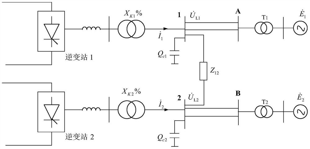
[0078] image 3 It is an equivalent circuit diagram of an AC-DC system for evaluating the risk of simultaneous commutation failure of multiple DC circuits according to another preferred embodiment of the present invention. Such as image 3 As shown, the AC-DC system in this preferred embodiment is a two-feed AC-DC system, the inverter side of the two-circuit DC power transmission system is connected to the adjacent same side, and the commutation bus on the inverter side is connected through an AC line. The rectifier sides are independent of each other. The sending-end system is an infinite power unit, and the receiving-end AC system model is represented by an equivalent potential source series transformer and a double-circuit AC line. exist image 3 Among them, the two feed-in AC and DC systems include DC system inverter side commutation bus 1 and commutation bus 2 and receiving end system AC bus A and AC bus B.

[0079] Figure 4 It is a flowchart of a method for evaluat...


PUM


Abstract

A method and system for evaluate that risk of simultaneous commutation failure of multiple DC circuits, A method and system for reduce that voltage coupling factor of a critical ac / dc system by calculate a voltage coupling factor of the ac / dc system and simplifying the voltage coupling factor of the critical ac / dc system, and comparing the voltage coupling action factor of the AC / DC system and thesimplified critical AC / DC voltage coupling action factor, judging whether each inverter side commutation bus of the DC system has the risk of simultaneous commutation failure according to the comparison result, the principles of the method and the system evaluation method are clear, Aiming at different AC busbars of the same HVDC system, the same simplified critical AC / DC system voltage couplingaction factor is obtained, which reduces the computational load and is convenient and fast. It is of great significance to guide the planning of large power network and to maintain the safe and stableoperation of large power network.

Description

technical field [0001] The present invention relates to the field of power system planning and operation, and more specifically, to a method and system for assessing the risk of simultaneous commutation failure of multiple DC circuits. Background technique [0002] With the development of DC transmission technology and the wide application of UHV AC and DC technology, multiple DC transmission systems have been placed on the same AC system at close distances in many regions of my country, that is, multi-infeed DC transmission systems. While increasing the flexibility of the system operation mode and expanding the transmission capacity of the system, the multi-infeed DC transmission also increases the complexity of the system structure. And due to the tight electrical coupling between DC inverter stations, the interaction between AC and DC systems becomes more complicated. The AC failure of the receiving end system may lead to the commutation failure of multiple DC circuits a...

Claims


Application Information

Patent Timeline
Patent Type & Authority Patents(China)
IPC IPC(8): H02J3/36
CPCH02J3/36Y02E60/60
Inventor 邵瑶周勤勇汤涌孙玉娇张一驰云雷王旭窦飞祁万春刘柏良李辰黄阮明黄一超
Owner CHINA ELECTRIC POWER RES INST
Features
  • R&D
  • Intellectual Property
  • Life Sciences
  • Materials
  • Tech Scout
  • Unparalleled Data Quality
  • Higher Quality Content
  • 60% Fewer Hallucinations
Learn More