Soot compression device having soot waste heat utilization function for electric dust removal tool

A compression device and electrostatic precipitator technology, applied in the direction of combined devices, dispersed particle separation, chemical instruments and methods, etc., can solve problems such as air pollution, heat loss, environmental pollution, etc., and achieve the effect of avoiding pollution and reducing waste heat

Inactive Publication Date: 2019-01-11
余汉锡
View PDF0 Cites 1 Cited by
  • Summary
  • Abstract
  • Description
  • Claims
  • Application Information

AI Technical Summary

Problems solved by technology

[0004] The object of the present invention is to provide a soot compression device for electric dust removal with the function of utilizing the waste heat of dust, so as to solve the problem that the existing dust compression device for electric dust removal proposed in the above background technology cannot replace the waste heat in the dust for secondary Recycling will not only cause heat loss, but also cause greater pollution to the environment, and will affect the compression effect of the soot, and in the process of compression, there will still be fine particles in the soot, so that the emitted soot will not Can meet the standard, will cause air pollution problems

Method used


Image

  • Soot compression device having soot waste heat utilization function for electric dust removal tool
  • Soot compression device having soot waste heat utilization function for electric dust removal tool
  • Soot compression device having soot waste heat utilization function for electric dust removal tool

Examples


Embodiment Construction

[0029] The following will clearly and completely describe the technical solutions in the embodiments of the present invention with reference to the accompanying drawings in the embodiments of the present invention. Obviously, the described embodiments are only some, not all, embodiments of the present invention. Based on the embodiments of the present invention, all other embodiments obtained by persons of ordinary skill in the art without making creative efforts belong to the protection scope of the present invention.

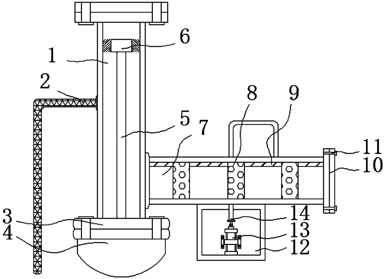
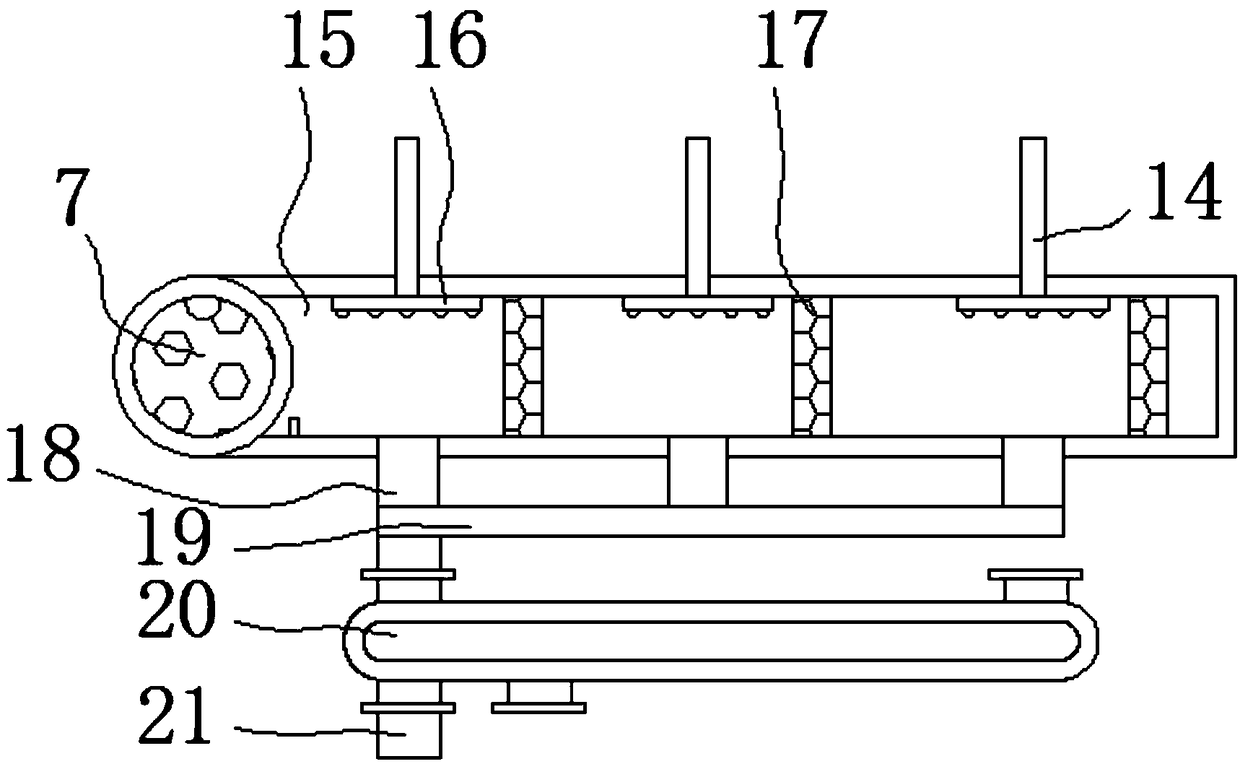
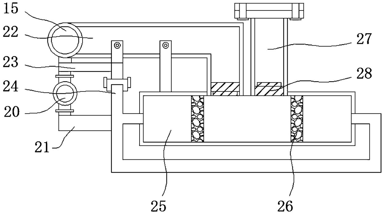
[0030] see Figure 1-5, the present invention provides a technical solution: a smoke compression device for electric dust removal with the function of utilizing smoke waste heat, including an air intake pipe 1, a ground wire 2, a connecting plate 3, a bottom valve 4, a connecting rod 5, a brush ring 6, Filter pipe 7, first filter plate 8, fixed rod 9, sealing plate 10, bolt 11, water tank 12, water pump 13, connecting pipe 14, waste heat recovery pipe 15, spra...


PUM


Abstract

The invention relates to a soot compression device having a soot waste heat utilization function for an electric dust removal tool. The soot compression device comprises an air inlet pipe and a connection pipe. The left side of the air inlet pipe is provided with a grounding wire. The lower end of the air inlet pipe is provided with a connection plate. A bottom valve is inlaid in the lower end ofthe connection plate. The middle of the upper end of the bottom valve is connected to a connection rod. The upper end of the connection rod is provided with a brush ring. The lower end of the right side of the air inlet pipe is fixedly provided with a filter pipe. Through the brush ring, the connection rod is fixed above the bottom valve and the outer side of the connection rod contacts with the inner wall of the air inlet pipe. When the bottom valve is dismounted, the brush ring is driven to slide from the upper end to the lower end in the air inlet pipe and the brush ring and the inner wallof the air inlet pipe generate friction so that the dust on the inner wall of the air inlet pipe can be removed through the brush ring, dust flowing influence caused by excessive impurities inside theair inlet pipe is prevented and the interior of the air inlet pipe can be cleaned regularly.

Description

technical field [0001] The invention relates to the technical field of a dust compression device for electric dust removal, in particular to a dust compression device for electric dust removal with the function of utilizing waste heat of smoke and dust. Background technique [0002] With the development of industry, it will bring a series of environmental protection problems. Smoke is a major problem in industrial emissions. Usually, electrostatic dust removal is used to remove particulate impurities in the smoke before discharge. After dust removal, the smoke is then compressed. However, the waste heat in the smoke will affect the compression effect, and if it is discharged into the air, it will pollute the natural environment, so the waste heat in the smoke needs to be removed. [0003] The existing dust compression device for electrostatic precipitator cannot replace the waste heat in the dust for secondary recycling, which not only causes heat loss, but also causes great...

Claims


Application Information

Patent Timeline
Patent Type & Authority Applications(China)
IPC IPC(8): B01D50/00
CPCB01D50/60
Inventor 余汉锡
Owner 余汉锡
Why Eureka
Try Eureka