Surface painting equipment for mechanical equipment

A technology of spraying equipment and mechanical equipment, which is applied in spray booths, pretreatment surfaces, devices for coating liquids on surfaces, etc., can solve problems such as inability to spray, failure to spray mechanical dead spots, and long paint drying time, and achieve waiting time. Less, avoid uneven spraying or omission, improve the effect of spraying effect

Inactive Publication Date: 2019-01-11
长兴曼尔申机械科技有限公司
0 Cites 2 Cited by

AI-Extracted Technical Summary

Problems solved by technology

However, the existing mechanical surface painting equipment cannot be sprayed according to the size of the machine and the distance from...

Abstract

The invention discloses surface painting equipment for mechanical equipment. The surface painting equipment comprises a control panel and an equipment body. The bottom end of the equipment body is provided with four universal wheels. The side wall of the equipment body is provided with a push/ pull door. The top end of the equipment body is provided with a rotating seat. The rotating seat is provided with a sliding wheel and is connected with the equipment body through the sliding wheel and a sliding groove. A first hydraulic rod is arranged below the rotating seat. A spraying gun is arrangedat the tail end of the first hydraulic rod and is connected with the first hydraulic rod through a fixed frame. The surface painting equipment for the mechanical equipment is provided with a stirringfork, rotary tables, a laser range finder, a small spraying head and an electric heating lamp, and machines with different sizes are placed on the rotary tables with different sizes for painting, so that the painting efficiency is higher; and the range finder can be used for adjusting appropriate spraying distances, the small spraying head is used to spray corners or dead angle positions to obtaina better surface effect, and paint drying is accelerated by the electric heating lamp.

Application Domain

Pretreated surfacesCoatings +1

Technology Topic

Electric heatingLaser ranging +5

Image

  • Surface painting equipment for mechanical equipment
  • Surface painting equipment for mechanical equipment
  • Surface painting equipment for mechanical equipment

Examples

  • Experimental program(1)

Example Embodiment

[0023] In order to make the technical means, creative features, goals and effects achieved by the present invention easy to understand, the present invention will be further described below in conjunction with specific embodiments.
[0024] In the description of the present invention, it should be noted that the terms "upper", "lower", "inner", "outer", "front end", "rear end", "both ends", "one end", "another end" The orientation or positional relationship indicated by etc. is based on the orientation or positional relationship shown in the drawings, and is only for the convenience of describing the present invention and simplifying the description, rather than indicating or implying that the referred device or element must have a specific orientation, use a specific Azimuth configuration and operation, therefore, should not be construed as limiting the invention. In addition, the terms "first" and "second" are used for descriptive purposes only, and should not be understood as indicating or implying relative importance.
[0025] In the description of the present invention, it should be noted that, unless otherwise specified and limited, the terms "installed", "set with", "connected", etc. should be understood in a broad sense, such as "connected", which may be a fixed connection , can also be detachably connected, or integrally connected; can be mechanically connected, can also be electrically connected; can be directly connected, can also be indirectly connected through an intermediary, and can be internal communication between two components. Those of ordinary skill in the art can understand the specific meanings of the above terms in the present invention in specific situations.
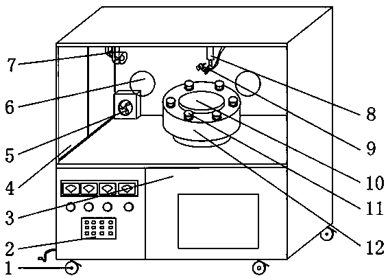
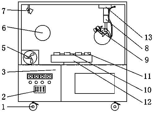
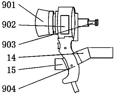
[0026] like Figure 1-7 As shown, a mechanical equipment surface painting equipment, including a control panel 2 and a device body 3, the bottom of the device body 3 is provided with four universal wheels 1, the side wall of the device body 3 is provided with a sliding door 4, the device body 3 The top of the rotating seat 13 is provided with a sliding wheel 22, and the rotating seat 13 is connected with the equipment body 3 through the sliding wheel 22 and the sliding groove, and the first hydraulic rod 8 is arranged under the rotating seat 13. The end of a hydraulic rod 8 is provided with a spray gun 9, and the spray gun 9 is connected with the first hydraulic rod 8 by a fixed mount 14, and the spray gun 9 includes a main spray head 901, a heater 902, a small spray head 903 and a handle 904, the main spray head 901 and the small spray gun 901. The nozzles 902 are all connected to the heater 903, and the handle 904 is fixed to the fixed frame 14. The fixed frame 14 is provided with a laser rangefinder 15, and the top of the equipment body 3 is located on one side of the sliding door 4. An electric heating lamp 7 is provided. A ventilating fan 5 is arranged under the electric heating lamp 7, a support seat 12 is arranged inside the equipment body 3, a motor 21 is arranged under the support seat 12, a gear set 16 is arranged inside the support seat 12, and the gear set 16 includes a first The gear 1601, the second gear 1602 and the third gear 1603, the top of the first gear 1601 and the third gear 1603 are respectively provided with a large turntable 10 and the small turntable 11, the bottom of the third gear 1603 is provided with a spring 20, the third gear 1603 A shift fork 18 is arranged on the top, and the shift fork 18 is connected with the third gear 1603 through the shift slot 19. One end of the shift fork 18 is provided with a second hydraulic rod 17, and the shift fork 18 is connected to the support seat 12 through the second hydraulic rod 17. Phase fixed;
[0027] The front end of the device body 3 is provided with a glass window 6, and there are two hand holes on the glass window 6; the output end of the motor 21 is connected with the first gear 1601 of the gear set 16, and the first gear 1601 passes through the second gear 1602 It is transmitted with six third gears 1603; the surface of the support seat 12 is provided with a large hole slightly larger than the diameter of the large turntable 10 and six small holes slightly larger than the diameter of the small turntable 11; the first hydraulic rod 8 can be changed by changing the rod length To change the position of the spray gun 9, and the rotating seat 13 moves along the slide groove in the equipment body 3 through the sliding wheel 22; the laser range finder 15 can measure the distance between the machine to be painted and the spray gun 9, and the spray gun 9 and the laser range finder 15 all form a certain angle with the first hydraulic rod 8; the second hydraulic rod 17 changes the position of the third gear 1603 by changing the length of the rod, and the diameter of the shift fork 18 matches the diameter of the shift groove 19; the lower end of the equipment body 3 The lower end of equipment body 3 such as being provided with power plug, indicator light and indicator and control panel 2 is provided with power plug, indicator light and indicator and control panel 2 etc.; Equipment body 3 is connected with external air purifier by ventilation fan 5.
[0028] It should be noted that the present invention is a painting equipment for the surface of mechanical equipment. When in use, the equipment body 3 is connected to the power supply, and the relevant parameters of the equipment are debugged and set through the control panel 2, and then the sliding door 4 is opened. The mechanical equipment to be sprayed is placed on the small turntable 11. At this time, the control panel 2 controls the spray gun 9 to move to the center of the six small turntable 11 under the cooperation of the sliding groove and the sliding wheel 22, and the spray gun 9 is measured by the laser distance meter 15. The distance to the mechanical surface, the system adjusts to a suitable distance, the motor 21 drives the gear set 16 to rotate to make the small turntable 11 rotate, the spray gun 9 sprays paint to the surface of the mechanical equipment, after spraying, the rotating seat 13 rotates at a certain angle, and the first spray Two pieces, now under the heating of the electric heating lamp 7 to speed up the drying of the paint, and so on until all the spraying is completed, when spraying larger mechanical equipment, it can be placed on the large turntable 10, and it can also be adjusted by adjusting the second The rod of the hydraulic rod 17 is long, and the third gear 1603 is moved to the bottom of the support seat 12 through the shift fork 18, so that the small turntable 11 is in the support seat 12, and the motor 21 drives the first gear 1601 to rotate, so that the large turntable 10 rotates , and control the rotating seat 13 to move around the mechanical equipment through the control panel 2, adjust the length of the first hydraulic rod 8, make the spray gun 9 face the surface of the mechanical equipment, and spray paint on the surface of the rotating equipment in sequence, the mechanical equipment There are some dead corners that cannot be sprayed, and the staff can extend their hands into the device body 3 through the hole of the glass window 6, take the spray gun 9 from the fixed frame 14, and use the small spray nozzle 903 to spray on the dead corners. After the completion, just move the shift fork 18 to the meshing position with the second gear 1602, and discharge the air in the device body 3 through the ventilation fan 5, and suck in the urgent air for use, which has a better effect.
[0029]The basic principles and main features of the present invention and the advantages of the present invention have been shown and described above. Those skilled in the industry should understand that the present invention is not limited by the above-mentioned embodiments. What are described in the above-mentioned embodiments and the description only illustrate the principle of the present invention. Without departing from the spirit and scope of the present invention, the present invention will also have Variations and improvements are possible, which fall within the scope of the claimed invention. The protection scope of the present invention is defined by the appended claims and their equivalents.

PUM

no PUM

Description & Claims & Application Information

We can also present the details of the Description, Claims and Application information to help users get a comprehensive understanding of the technical details of the patent, such as background art, summary of invention, brief description of drawings, description of embodiments, and other original content. On the other hand, users can also determine the specific scope of protection of the technology through the list of claims; as well as understand the changes in the life cycle of the technology with the presentation of the patent timeline. Login to view more.

Similar technology patents

Fire-resistant paint spraying device for cables

InactiveCN110918294AImprove spraying efficiency
Owner:STATE GRID CHONGQING ELECTRIC POWER CO ELECTRIC POWER RES INST +1

Pesticide applying vehicle

InactiveCN107853273AImprove spraying efficiencyImprove application efficiency
Owner:王天行

Corn pesticide spraying device and operation method

ActiveCN114868721AGood at removing pests and diseasesImprove spraying efficiency
Owner:FARMING & CULTIVATION RES INST OF HEILONGJIANG ACADEMY OF AGRI SCI

Classification and recommendation of technical efficacy words

  • Improve spraying efficiency

Cable rope coating spraying device and method

PendingCN109395942AImprove spraying efficiencyGood spray effect
Owner:SOUTHWEST JIAOTONG UNIV

Pesticide spraying device for agriculture

Owner:广西永福金穗生态农业发展有限公司

Expanding device

ActiveCN104907426AImprove spraying efficiency
Owner:SHENZHEN WOER HEAT SHRINKABLE MATERIAL +1
Why Eureka
Try Eureka