
Sewage salvage device for energy storage power station reservoir

A technology of energy storage power station and salvage device, which is applied in water conservancy projects, cleaning of open water surface, construction, etc. It can solve the problems of easy access and damage to the pump unit, affecting the ecological environment of the reservoir, and affecting the efficiency of salvage, etc., so as to achieve convenient use, Novel design and strong practicability

Pending Publication Date: 2019-01-11
STATE GRID CORP OF CHINA +2
View PDF1 Cites 3 Cited by
  • Summary
  • Abstract
  • Description
  • Claims
  • Application Information

AI Technical Summary

Problems solved by technology

[0003] Since the reservoir of the energy storage power station is open, there is a lot of dirt floating on the water surface of the reservoir, which not only affects the ecological environment of the reservoir, but also easily enters and damages the pump unit. The existing technology is to salvage manually To clean up the suspended dirt in the reservoir, time-consuming, laborious and inefficient
[0004] The utility model patent with the publication number CN207244596U discloses a suspended garbage cleaning device for a pumped storage power station. This device can effectively clean up the suspended garbage in the reservoir, but when salvaging large areas of dirt on the water surface, it is necessary to continuously move the hull and reduce It not only improves the convenience of use, but also affects the efficiency of salvage

Method used


Image

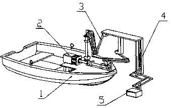
  • Sewage salvage device for energy storage power station reservoir
  • Sewage salvage device for energy storage power station reservoir
  • Sewage salvage device for energy storage power station reservoir

Examples


Embodiment Construction

[0029] In order to make the object, technical solution and advantages of the present invention clearer, the implementation manner of the present invention will be further described in detail below in conjunction with the accompanying drawings.

[0030] It should be noted that, in the case of no conflict, the embodiments of the present invention and the features in the embodiments can be combined with each other.

[0031]In describing the present invention, it should be understood that the terms "center", "longitudinal", "transverse", "upper", "lower", "front", "rear", "left", "right", The orientations or positional relationships indicated by "vertical", "horizontal", "top", "bottom", "inner", "outer", etc. are based on the orientation or positional relationships shown in the drawings, and are only for the convenience of describing the present invention Creation and simplification of description, rather than indicating or implying that the device or element referred to must hav...


PUM


Abstract

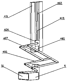
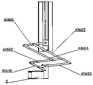
The invention discloses a sewage salvage device for an energy storage power station reservoir, and belongs to the technical field of energy storage power stations. According to the technical scheme, the sewage salvage device for the energy storage power station reservoir comprises a ship, a driving mechanism is arranged on the ship, the driving mechanism is connected with a horizontal movement mechanism, the horizontal movement mechanism is arranged on the upper portion of the ship, the horizontal movement mechanism is connected with a vertical adjusting mechanism, the horizontal movement mechanism drives the vertical adjusting mechanism to horizontally move, the vertical adjusting mechanism is arranged on one side of the ship, the bottom end of the vertical adjusting mechanism is connected with a cleaning box, and the vertical adjusting mechanism is used for adjusting the depth of the cleaning box entering the water surface of the reservoir. The technical scheme has the beneficial effects of being simple in structure, novel in design, high in practicability and convenient to use, floating garbage on the water surface of the energy storage power station reservoir can be effectivelyfished, the labor force is reduced, and the efficiency is improved.

Description

technical field [0001] The invention relates to the technical field of energy storage power stations, in particular to a sewage salvage device for reservoirs of energy storage power stations. Background technique [0002] A pumped storage hydropower station is a hydropower station that uses electric energy to pump water to the upper reservoir when the power load is low, and then releases water to the lower reservoir for power generation during the peak period of the power load. It is also called an energy storage hydropower station. It can transform the excess electric energy when the grid load is low into high-value electric energy during the peak period of the grid. It is also suitable for frequency modulation and phase modulation, stabilizing the cycle and voltage of the power system, and it is suitable for emergency backup. It can also improve thermal power plants in the system and the efficiency of nuclear power plants. [0003] Since the reservoir of the energy storag...

Claims


Application Information

Patent Timeline
IPC IPC(8): E02B15/10B63B35/32
CPCE02B15/10B63B35/32
Inventor 杨艳平陈鑫郑小贺庄广明
Owner STATE GRID CORP OF CHINA
Learn More