Reaming device for oil and gas drilling

An oil and natural gas and drilling technology, which is applied to drilling equipment, drill bits, drill pipes, etc., can solve the problems such as the inability to improve the operation efficiency and operation quality of the device, the reduction of the practicability of the device, and the complex overall structure, so as to improve the efficiency and expand the The effect of eye quality, reduction of strain and expansion of working range

Inactive Publication Date: 2019-01-11
兴城市祥安畜牧养殖有限公司
View PDF0 Cites 7 Cited by
  • Summary
  • Abstract
  • Description
  • Claims
  • Application Information

AI Technical Summary

Problems solved by technology

[0002] With the deepening of the understanding of the mechanism of oil and gas accumulation and the development of oil and gas fields, the problems encountered in drilling are becoming more and more complex, and the solutions to these complex problems are increasingly dependent on the development of tools and means. Proposed and developed based on this background, the so-called reaming-while-drilling technology is a drilling technology that uses reaming-while-drilling tools and conventional drill bit procedures to expand the wellbore while fully drilling. There is a lack of drilling devices, and the operating performance is relatively simple. Although the traditional drilling reaming device has achieved the basic reaming operation, the overall structure is relatively complicated and the volume is large. This not only easily leads to device failure, but also has poor flexibility and disadvantages. The movement reduces the practicability of the device. At the same time, the traditional drilling and reaming technology cannot enable the staff to quickly grasp the internal situation of the drilling, resulting in the failure of the device's operating efficiency and quality to be improved.

Method used


Image

  • Reaming device for oil and gas drilling
  • Reaming device for oil and gas drilling
  • Reaming device for oil and gas drilling

Examples


Embodiment Construction

[0014] The following will clearly and completely describe the technical solutions in the embodiments of the present invention with reference to the accompanying drawings in the embodiments of the present invention. Obviously, the described embodiments are only some, not all, embodiments of the present invention. Based on the embodiments of the present invention, all other embodiments obtained by persons of ordinary skill in the art without making creative efforts belong to the protection scope of the present invention.

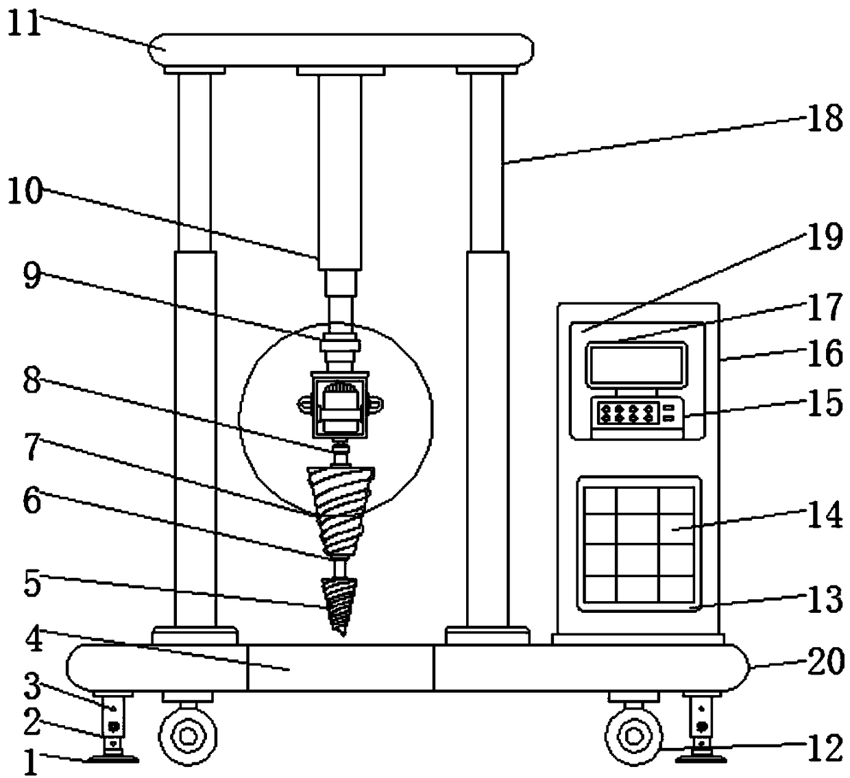
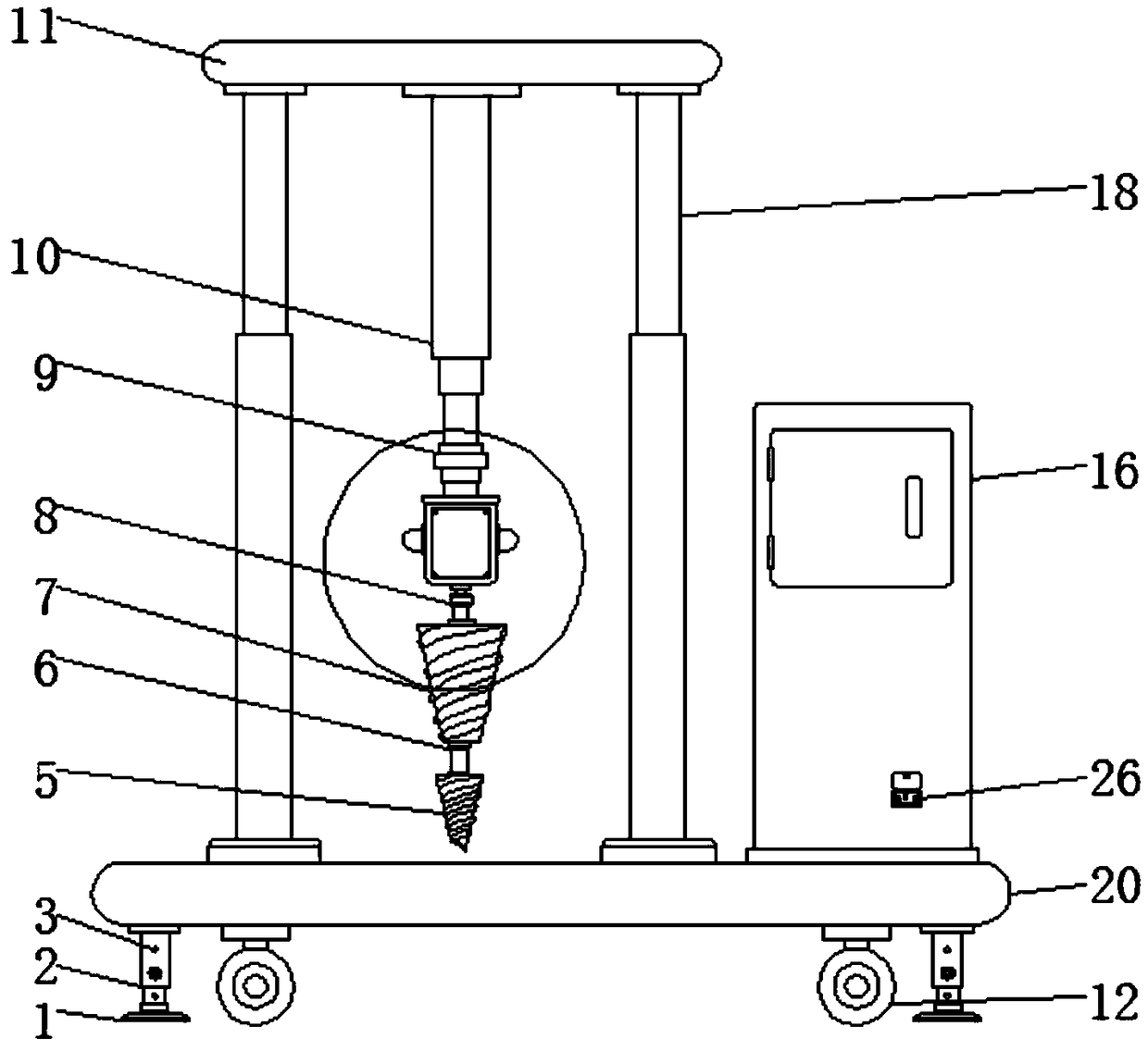
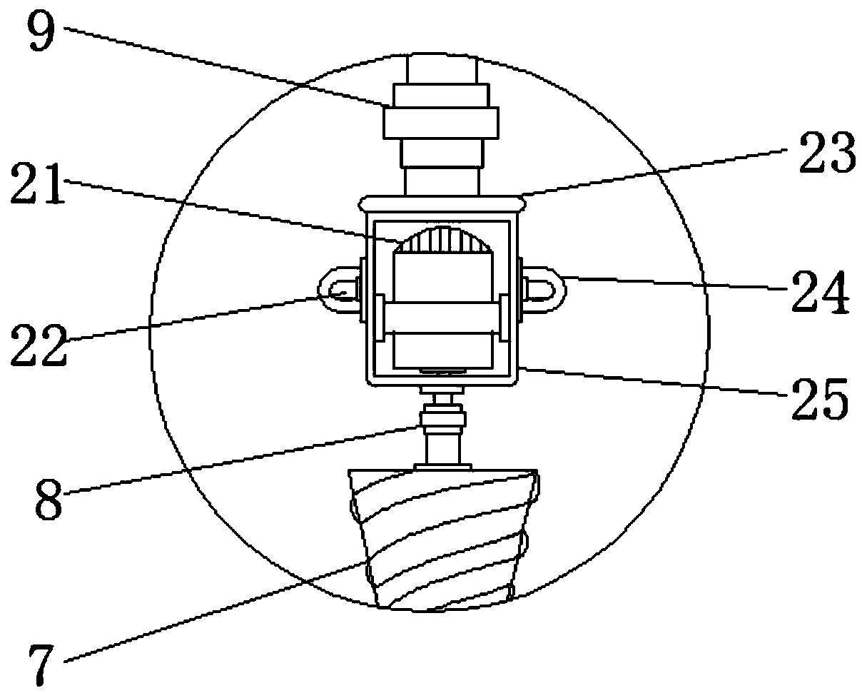
[0015] see Figure 1-3 , an embodiment provided by the present invention: a reaming device for oil and gas drilling, including a second conical drill bit 7, a first hydraulic telescopic rod 10, a mounting plate 11, a mounting shell 16 and a base 20, the bottom of the base 20 Both sides of the telescopic rod 2 are installed, and the limited holes 3 are evenly distributed on the telescopic rod 2. The bottom of the telescopic rod 2 is equipped with a fixed foot 1...


PUM


Abstract

The invention discloses a reaming device for oil and gas drilling. The device includes a second conical drill bit, first hydraulic telescopic rods, a mounting plate, a mounting shell and a base, wherein telescopic rods are mounted on both sides of the bottom of the base, limit holes are evenly distributed on the telescopic rods, the bottom of the telescopic rods is equipped with fixing pins, walking wheels are mounted at the bottom of the base among the telescopic rods, the top of the base is equipped with a mounting plate through two sets of second hydraulic telescopic rods, and the central position of the bottom of the mounting plate is equipped with the first hydraulic telescopic rods. The device is advantaged in that through the second conical drill bit, the first hydraulic telescopicrods, the mounting plate, the mounting shell and the base, the walking wheels can facilitate the staff to quickly transfer the device according to the actual situation, the hydraulic telescopic rods can be adjusted and lifted according to the working condition, cameras can facilitate the staff to observe the internal drilling situation when the device is in operation, and the device has strong practicability and is worth popularizing.

Description

technical field [0001] The invention relates to the technical field of drilling and reaming, in particular to a reaming device for oil and gas drilling. Background technique [0002] With the deepening of the understanding of the mechanism of oil and gas accumulation and the development of oil and gas fields, the problems encountered in drilling are becoming more and more complex, and the solutions to these complex problems are increasingly dependent on the development of tools and means. It is proposed and developed based on this background that the so-called reaming-while-drilling technology is a drilling technology that uses reaming-while-drilling tools and conventional drill bit procedures to expand the wellbore while fully drilling. There is a lack of drilling devices, and the operating performance is relatively simple. Although the traditional drilling reaming device has achieved the basic reaming operation, the overall structure is relatively complicated and the volum...

Claims


Application Information

Patent Timeline
Patent Type & Authority Applications(China)
IPC IPC(8): E21B7/28E21B7/02E21B47/002E21B47/017E21B19/086E21B10/26
CPCE21B7/02E21B7/28E21B10/26E21B19/086E21B47/002E21B47/017
Inventor 张国振周丽丽李明阳
Owner 兴城市祥安畜牧养殖有限公司
Why Eureka
Try Eureka