Shield machine cutterhead

A shield machine and cutter head technology, which is applied in mining equipment, earthwork drilling, tunnels, etc., can solve the problems of main force-bearing surface and tool wear, short service life of cutter head and tool, and large stress, etc., to achieve reduction The effect of degree of wear

Active Publication Date: 2019-01-11
浙江中铁工程装备有限公司
View PDF7 Cites 14 Cited by
  • Summary
  • Abstract
  • Description
  • Claims
  • Application Information

AI Technical Summary

Problems solved by technology

[0005] The invention provides a cutter head of a shield machine, which is capable of carrying out component-type excavation and crushing work on the tunnel rock layer during the tunnel excavation process, and reduces the stress and wear on the main force-bearing surface of the cutter head and the cutter during the tunnel excavation process. The advantage of solving the problem is that the cutter head of the existing shield machine is a disc-shaped planar structure. When the propulsion system of the shield machine drives the cutter head to excavate the soil and gravel layer, even if the size and shape of the cutter on the cutter head The design is different, and the gravel can be cut step by step. However, during the advancement and excavation of the shield machine, the main excavation surface of the cutter head and the cutter on the same plane on the cutter head are subjected to a large stress at the same time, resulting in the cutter head and the cutter being in the same plane. During the excavation process, the main force-bearing surface and the tool are severely worn, and the service life of the cutter head and the tool is short.

Method used


Image

  • Shield machine cutterhead
  • Shield machine cutterhead
  • Shield machine cutterhead

Examples


Embodiment Construction

[0031] The following will clearly and completely describe the technical solutions in the embodiments of the present invention with reference to the accompanying drawings in the embodiments of the present invention. Obviously, the described embodiments are only some, not all, embodiments of the present invention. Based on the embodiments of the present invention, all other embodiments obtained by persons of ordinary skill in the art without making creative efforts belong to the protection scope of the present invention.

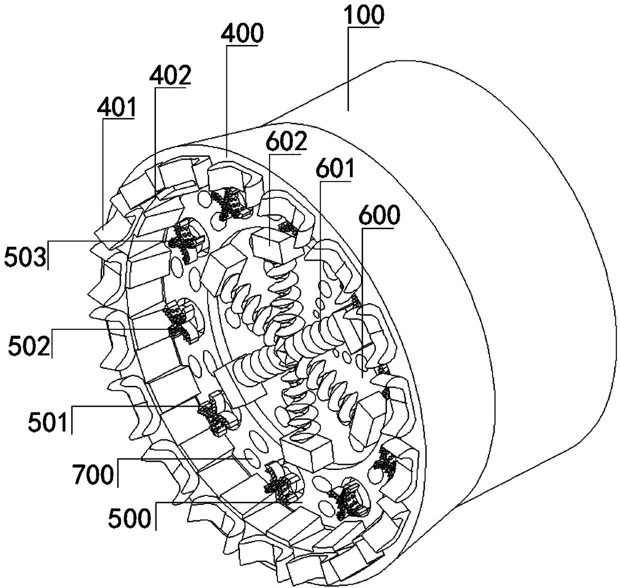
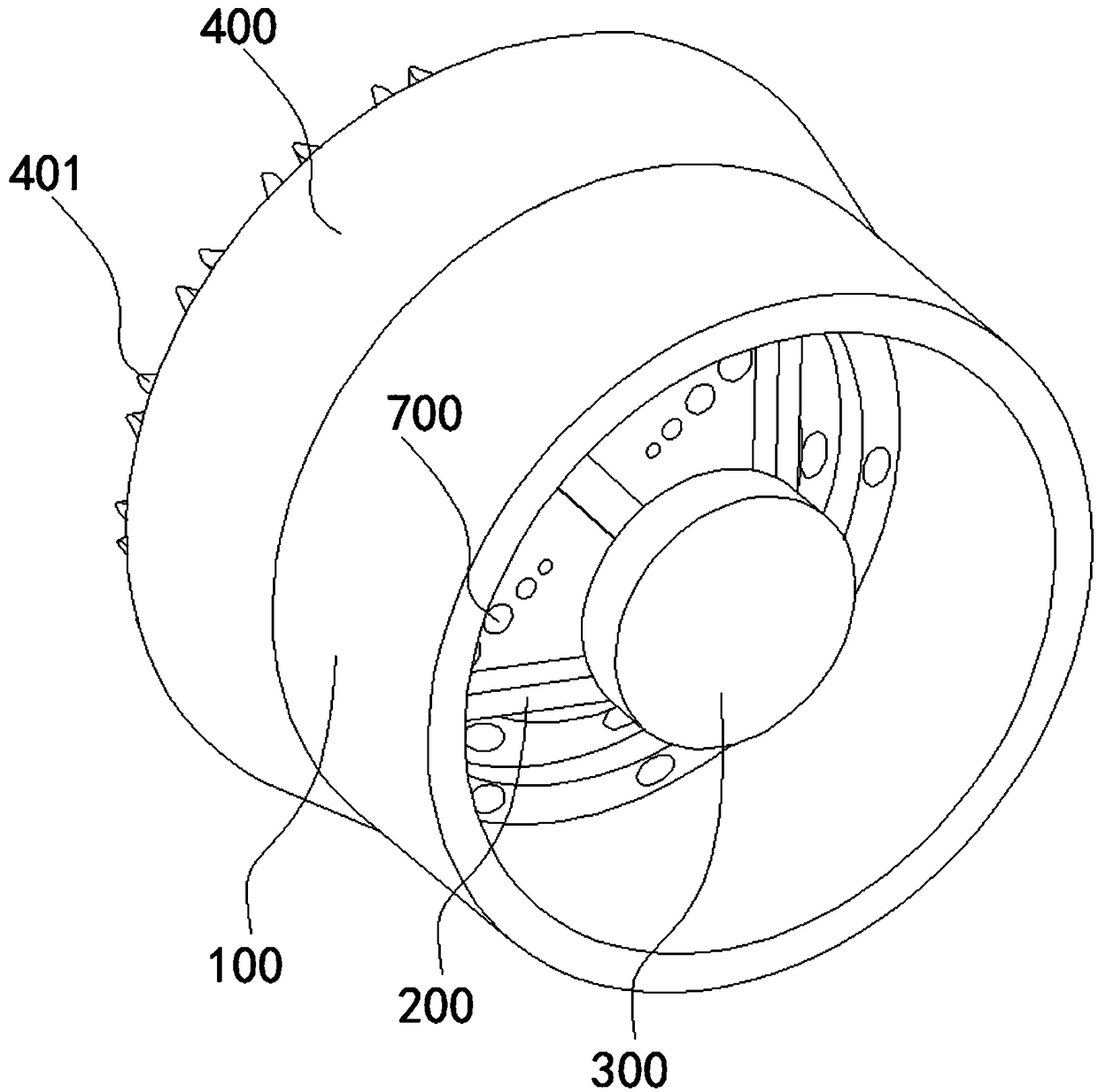
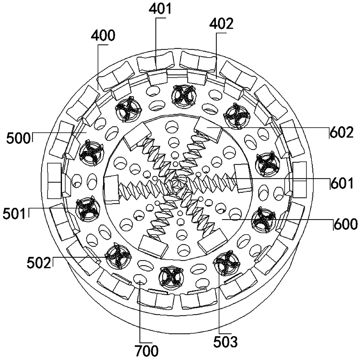
[0032] see Figure 1-8 , a shield machine cutterhead, including a shield machine cutterhead shell 100, a receiving rotating rod 200 and a connecting turntable 300, the shield machine cutterhead shell 100 is composed of an outer diameter limiting cutterhead 400, an inner grinding cutterhead 500, The central cutterhead 600 and the screening leakage hole 700 are formed, and the outer diameter limiting cutterhead 400, the inner grinding cutterhead 500 and the cent...


PUM


Abstract

The invention relates to the technical field of tunneling equipment and discloses a shield machine cutterhead. The shield machine cutterhead includes a shield machine cutterhead shell, a receiving turning rod and a connecting turntable, wherein the shield machine cutterhead shell is composed of an outer diameter limiting cutterhead, an inner grinding cutterhead, a central cutterhead and a screening leak hole, the outer diameter limiting cutterhead, the inner grinding cutterhead and the central cutterhead are sequentially nested from the outside to the inside of an inner cavity of the shield machine cutterhead shell, and the outer diameter limiting cutterhead includes an outer diameter limiting cutter and a diversion chute. The shield machine cutterhead is advantaged in that through steppedtunneling and crushing components of the outer diameter limiting cutterhead, the inner grinding cutterhead and the central cutterhead, the tunnel is tunneled and crushed at first, second and third stages in a stepped mode in the working process of the cutterhead driven by a working shield machine, the stress and torsion of crushing cutters such as outer diameter limiting cutters, main crushing cutters and secondary crushing cutters on the cutterhead in the tunneling and crushing process are reduced, and the wear rate of the crushing cutters in the tunneling process is reduced.

Description

technical field [0001] The invention relates to the technical field of tunneling equipment, in particular to a shield machine cutterhead. Background technique [0002] The shield machine is an engineering device for tunnel excavation. It is mainly composed of a shield machine cutter head, a front shield and a back shield. dig. [0003] The existing shield machine cutter head has a disc-shaped planar structure. When the shield machine propulsion system drives the cutter head to excavate the soil and gravel layer, the shield machine cutter head and the cutter on the cutter head excavate the gravel. Cutting, although the sizes and shapes of the cutters on the cutterhead are different, the main driving surface of the cutterhead and the cutters on the cutterhead are respectively located on the same plane. During the advancement and excavation of the shield machine, the cutterhead and the cutter , Directly bear the grinding force of the tunnel rock as a whole, causing the main s...

Claims


Application Information

Patent Timeline
Patent Type & Authority Applications(China)
IPC IPC(8): E21D9/08
CPCE21D9/08
Inventor 不公告发明人
Owner 浙江中铁工程装备有限公司
Why Eureka
Try Eureka