
LED lamp

A technology of LED lamps and LED chips, which is applied in lighting devices, cooling/heating devices of lighting devices, light sources, etc., can solve the problems of inability to dissipate heat from thermal fluid and low heat dissipation effect of LED lamps, and achieve improved heat dissipation and heat dissipation The effect is obvious and the effect of delaying the return speed

Pending Publication Date: 2019-01-11
葛成燕
View PDF6 Cites 2 Cited by
  • Summary
  • Abstract
  • Description
  • Claims
  • Application Information

AI Technical Summary

Problems solved by technology

[0004] In order to make up for the shortcomings of the existing technology and solve the problem that the heat dissipation effect of LED lamps is not high, and the heat dissipation of the thermal fluid cannot be achieved, so as to achieve overall heat dissipation, the present invention provides a technical solution to solve this problem

Method used


Image

  • LED lamp

Examples


Embodiment approach

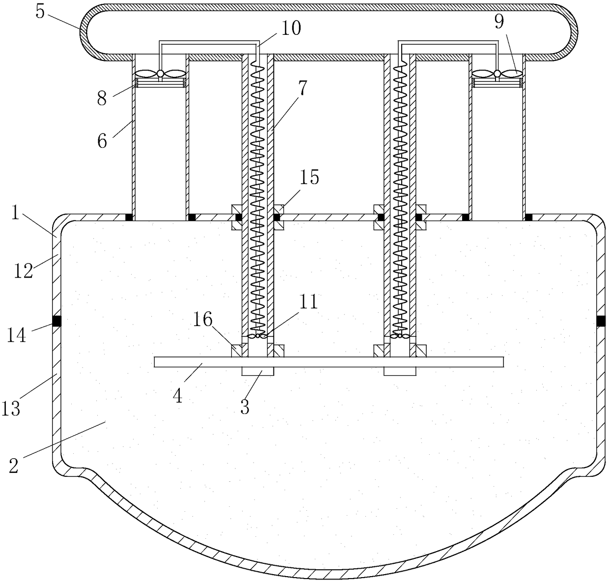
[0021] As an embodiment of the present invention, the metal substrate 4 and the return pipe 7 are fixedly connected by the No. 2 nut 16, and the No. 2 nut 16 is fixed on the upper end surface of the metal substrate 4. Tube 7 is locked.

[0022]As an embodiment of the present invention, the flexible shaft 10 is made of soft material. When the large fan 9 rotates, the soft shaft 10 is driven to rotate in a spiral shape, and the flexible shaft 10 returns to its original state to rotate, and then drives the small fan 11 to rotate. The part of the soft material located in the return pipe 7 is provided with a helical thread, and when the flexible shaft 10 rotates, the helical thread can delay the return velocity and speed up the gas flow rate, thereby achieving the effect of cooling the heat transfer fluid 2.

[0023] As an embodiment of the present invention, the inner diameter of the outlet pipe 6 is larger than the inner diameter of the return pipe 7 , which can ensure that the h...


PUM


Abstract

The invention belongs to the technical field of optoelectronic devices, and particularly relates to an LED lamp. Since LED chips generate heat by emitting light, the heat dissipation range is expandedby a metal substrate, and as the temperature rises, heat conduction fluid volatilizes and flows into an airbag through air outlet pipes; volatilized gas drives large fans to rotate, the large fans rotate to accelerate gas flow, and the heat dissipation effect is improved. The gas enters the airbag, the airbag expands to increase the inner space of the airbag, the contact area of the airbag and the outside words is increased, the gas is in contact with the inner wall of the airbag, and the heat dissipation effect is improved. The heat conduction fluid passes through return pipes by cooling, and due to the rotation of flexible shafts, the rotation of the flexible shafts in the return pipes can effectively slow down the back-flow velocity and increase the cooling time; and at the same time,the rotation of small fans further improves the efficiency of heat dissipation and cooling. After cooling, the reflowed heat conduction fluid performs cooling on the metal substrate once on the one hand, and on the other hand, the reflowed heat conduction fluid flows back to a glass container, and heat conduction fluid in the glass container is further cooled, so that the purpose of cooling the lamp is achieved.

Description

technical field [0001] The invention belongs to the technical field of optoelectronic devices, in particular to an LED lamp. Background technique [0002] A light-emitting diode (Light-EmittingDiode, LED) is a semiconductor component. At the beginning, it was mostly used as indicator lights, display light-emitting diode boards, etc.; with the emergence of white LEDs, it was also used as lighting. In the LED lighting system, the decisive factor that determines its luminescence and service life is the heat dissipation of the chip, so the heat dissipation of LED lamps has always been the focus of attention. The aluminum heat dissipation structure used in the early days used multiple heat sinks to make waves or folds to increase the contact area with the air, thereby reducing the chip temperature. With the increase of LED chip power, heat production also increases, and the original aluminum heat dissipation structure lamps can no longer meet the requirements. In order to impr...

Claims


Application Information

Patent Timeline
Patent Type & Authority Applications(China)
IPC IPC(8): F21K9/20F21V29/67F21V29/58F21Y115/10
CPCF21K9/20F21V29/58F21V29/67F21Y2115/10
Inventor 葛成燕
Owner 葛成燕
Learn More