Grating spectrometer image quality measuring method and device

A grating spectrometer and measuring device technology, applied in the optical field, can solve the problems of inability to test the transfer function of the spectral direction, unable to apply the optical transfer function test, unable to form the edge spread function, etc., to achieve the effect of accurate testing

Active Publication Date: 2019-01-11
BEIJING RES INST OF SPATIAL MECHANICAL & ELECTRICAL TECH
View PDF5 Cites 6 Cited by
  • Summary
  • Abstract
  • Description
  • Claims
  • Application Information

AI Technical Summary

Problems solved by technology

For imaging spectrometers, this method can be used to test the spatial direction transfer function. The spectral direction is limited by the slit. The width of the slit is equivalent to the size of the detector pixel. Only one bright or dark line can pass through the bright and dark stripes of the rectangular target. Causes the transfer function in the spectral direction to be untestable
For other test methods such as the edge method, due to the limitation of the slit of the imaging spectrometer, an effective edge spread function cannot be formed and cannot be applied to the optical transfer function test in the spectral direction of the imaging spectrometer
At present, there is no effective test method for the spectral direction of the imaging spectrometer. Generally, the optical transfer function of the spatial direction is used to estimate the optical transfer function of the spectral direction, and the optical transfer function of the spectral direction is comprehensively determined in combination with the spectral resolution of the spectral direction.

Method used


Image

  • Grating spectrometer image quality measuring method and device
  • Grating spectrometer image quality measuring method and device
  • Grating spectrometer image quality measuring method and device

Examples


Embodiment Construction

[0025] Exemplary embodiments of the present disclosure will be described in more detail below with reference to the accompanying drawings. Although exemplary embodiments of the present disclosure are shown in the drawings, it should be understood that the present disclosure may be embodied in various forms and should not be limited by the embodiments set forth herein. Rather, these embodiments are provided for more thorough understanding of the present disclosure and to fully convey the scope of the present disclosure to those skilled in the art. It should be noted that, in the case of no conflict, the embodiments of the present invention and the features in the embodiments can be combined with each other. The present invention will be described in detail below with reference to the accompanying drawings and examples.

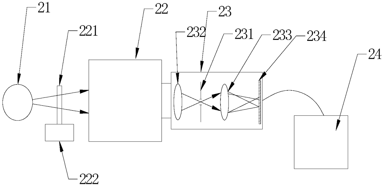
[0026] figure 1 It is a schematic diagram of the principle of the optical transfer function testing method of the imaging camera provided by the embodiment o...


PUM


Abstract

The invention discloses a high precision grating spectrometer image quality measuring method and device. The device comprises a monochromatic light source which is homogenized by an integrating sphere, a collimator with a slit target, a tested imaging spectrometer and a data processing system. The slit target is controlled by a micro-displacement table to translate along a direction vertical to aslit of the tested spectrometer. The tested spectrometer can receive a signal of the monochromatic light source, wherein the signal passes the slit target. Through analysis and computing of a relationship between light intensity change of certain group of pixels on the spectrometer and slit movement amount, a line spread function of the spectrometer is obtained; influence of width of the slit target on a test result is removed; and through Fourier transform, an MTF of a system spectrum direction is computed. The object slit is rotated for 90 degrees and scanning is carried out, so the MTF of aspace direction can be tested. According to the method, the problem that a transfer function of the spectrum direction of the imaging spectrometer cannot be tested can be solved, and a precise test for image quality of the imaging spectrometer is realized.

Description

technical field [0001] The invention belongs to the field of optical technology, in particular to a method and device for measuring the image quality of a grating spectrometer. Background technique [0002] With the development of optical remote sensing technology, spectral measurement technology has been applied and developed in material composition analysis, environmental monitoring, geological survey and military reconnaissance, especially space-borne or airborne spectral imagers have been widely used in space detection Application, the imaging spectrometer can acquire the two-dimensional spatial image and one-dimensional spectral information of the target at the same time, which can not only directly reflect the geometric shape of the measured target, but also provide the physical and chemical properties of the target. It is a detection method combining graphs and spectra. Since the 1980s, spectral imaging technology has been widely used in aerospace remote sensing imagi...

Claims


Application Information

Patent Timeline
Patent Type & Authority Applications(China)
IPC IPC(8): G01J3/02
CPCG01J3/02
Inventor 杜国军王春雨董欣张超范龙飞贾馨欧宗耀崔程光张志飞陆玉婷陈宗
Owner BEIJING RES INST OF SPATIAL MECHANICAL & ELECTRICAL TECH
Why Eureka
Try Eureka