Valve detection device and use method thereof

A detection device and valve technology, which is applied in the direction of measuring device, mechanical valve test, optical device, etc., can solve the problems of simplification of detection function, unclear detection information, low detection efficiency, etc., and achieve diversified functions and high detection accuracy , the effect of reducing labor intensity

Inactive Publication Date: 2019-01-11
天津百诚阀门制造股份有限公司
View PDF1 Cites 6 Cited by
  • Summary
  • Abstract
  • Description
  • Claims
  • Application Information

AI Technical Summary

Problems solved by technology

[0007] In the actual use of the above patents, there are problems such as low detection efficiency, unclear detection information, still need t...

Method used


Image

  • Valve detection device and use method thereof
  • Valve detection device and use method thereof
  • Valve detection device and use method thereof

Examples


Embodiment 1

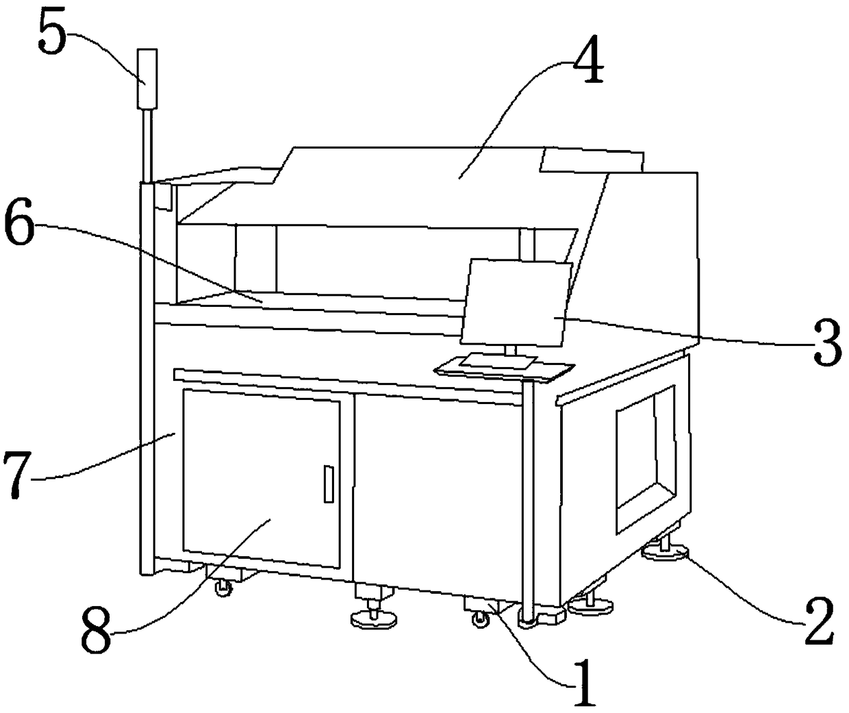
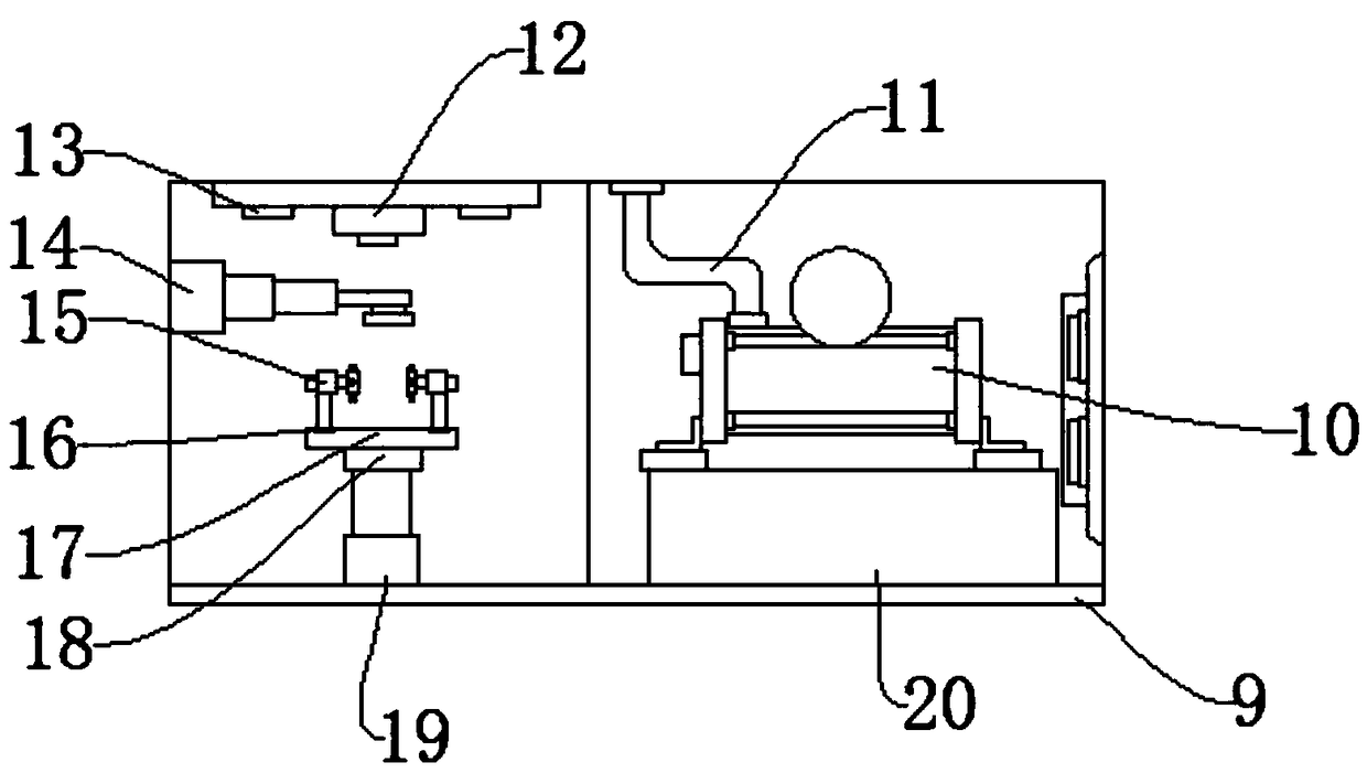
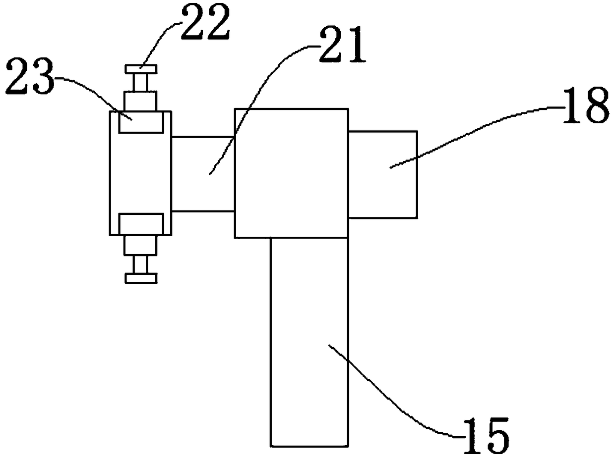
[0036] Such as Figure 1-Figure 6 As shown, a valve detection device includes a base 7, a detection platform 6, and a sealing cover 4. An alarm indicator 5 is arranged on the outer side wall of the base 7, and a controller is arranged on one side of the alarm indicator 5. 3. A moving pulley 1 is set under the base 7, a stable base 2 is set on one side of the moving pulley 1, a size detection chamber 8 is set at the bottom of the base 7, and a height is set inside the size detection room 8. Regulate the hydraulic cylinder 19, the top of the height adjustment hydraulic cylinder 19 is provided with a rotating motor 18, the specific model of the rotating motor 18 is ZYTD-38SRZ-R, the top of the rotating motor 18 is provided with a rotating disc 17, and the rotating disc 17 top is provided with weight detector 16, and the specific model of described weight detector 16 is I8001, and above described weight detector 16 is provided with fixer 15, and described fixer 15 is provided with...

Embodiment 2

[0038] The difference between this implementation and Embodiment 1 is:

[0039] The grasping head 24 is provided with a groove for fixing the opening arm of the valve, and the side wall of the size detection chamber 8 is provided with an opening and closing door for sealing.

[0040] Specifically, such setting can facilitate the detection of opening and closing of the valve body, improve the use effect of the equipment, facilitate the installation and disassembly of the valve body, and simplify the operation process.

[0041] The present invention also provides a method of using a valve detection device, which is applied to the above-mentioned valve detection device. The specific method of use is as follows: when starting the detection, the operator opens the opening and closing door on the size detection chamber 8, and it will be necessary to carry out The valve for detection processing is nested and connected to the holder 15, and then the pressure plate 22 and the clamping ...


PUM


Abstract

The invention discloses a valve detection device and a use method thereof. The valve detection device comprises a base platform, a detection table and a sealing cover, wherein an alarm indicator lampis arranged on the outer side wall of the base platform; a controller is arranged on one side of the alarm indicator lamp, and moving pulleys are arranged below the base platform; stabilizing bases are arranged on one sides of the moving pulleys; a size detection chamber is arranged at the bottom of the base platform, and a height adjustment hydraulic cylinder is arranged in the size detection chamber; a rotating motor is arranged above the height adjustment hydraulic cylinder, and a rotating disk is arranged above the rotating motor; a weight detector is arranged at the top of the rotating disk; and a fixing device is arranged above the weight detector. The valve detection device and the use method thereof have the beneficial effects that 1, the device has reasonable structural design, small occupied area, low installation difficulty and simple operation; 2, the device has diversified detection functions and high detection precision, thereby remarkably reducing the labor intensity ofworkers; and 3, the device has a long service life, low failure rate, high intelligence degree and high practicability.

Description

technical field [0001] The invention relates to the technical field of valve detection equipment, in particular to a valve detection device and a method for using the same. Background technique [0002] Valves are pipeline accessories used to open and close pipelines, control flow direction, adjust and control the parameters (temperature, pressure and flow) of the conveying medium. According to its function, it can be divided into shut-off valve, check valve, regulating valve and so on. [0003] The valve is a control component in the fluid delivery system, which has functions such as cut-off, adjustment, flow diversion, reverse flow prevention, pressure stabilization, flow diversion or overflow pressure relief. Valves used in fluid control systems range from the simplest cut-off valves to various valves used in extremely complex automatic control systems, with a wide variety of varieties and specifications. [0004] Valves can be used to control the flow of various types ...

Claims


Application Information

Patent Timeline
IPC IPC(8): G01M13/003G01B11/00G01G19/00
CPCG01M13/00G01B11/00G01G19/00
Inventor 王建军
Owner 天津百诚阀门制造股份有限公司
Why Eureka
Try Eureka