Three-dimensional unsteady slurry grouting test device and method

A grouting test, an unsteady technology, applied in the direction of measuring devices, applying stable tension/pressure to test the strength of materials, instruments, etc., can solve the problem of not being able to reflect the diffusion law of grout, not considering the performance parameters of grout, and not being able to observe the grout of the device in real time Diffusion flow and the expansion process of cracks, etc., to achieve the effect of easy direct observation, good promotion prospects, and simple structure

Pending Publication Date: 2019-01-11
CHINA UNIV OF MINING & TECH
View PDF6 Cites 4 Cited by
  • Summary
  • Abstract
  • Description
  • Claims
  • Application Information

AI Technical Summary

Problems solved by technology

At present, most of the researches on grouting theory and grouting test assume that parameters such as grout performance parameters (viscosity coefficient, dehydration solidification) and crack shape parameters are constant, and the cracks in the actual engineering surrounding rock mass are simplified to a single smooth shape However, the research on the law of seepage and diffusion of grout cannot truly reflect the changes in the grout parameters caused by the dehydration and hardening of the grout during the flow and diffusion process, and the differences in the shape parameters of the cracks, and cannot reflect the diffusion law of the grout in the actual project.
[0003] At present, due to the influence of factors such as test conditions and test objects, the existing grouting test device is basically used to simulate the compaction penetration grouting test under the medium constraint condition of small-scale coal and rock mass and the grouting test under the large-scale unconstrained condition. The free diffusion test did not take into account the changes in grout performance parameters over time (viscosity coefficient, dehydration condensation hardening), crack shape parameters (crack surface roughness, crack filling, crack space distribution) on the grouting process and surrounding conditions. The extrusion effect (constraint effect) of coal and rock mass on the injected area
In addition, most of the existing grouting test devices are opaque structures, and it is impossible to observe the diffusion flow of the grout inside the device and the expansion process of the cracks in real time.

Method used


Image

  • Three-dimensional unsteady slurry grouting test device and method
  • Three-dimensional unsteady slurry grouting test device and method
  • Three-dimensional unsteady slurry grouting test device and method

Examples


Embodiment Construction

[0024] In order to make the object, technical solution and advantages of the present invention clearer, the present invention will be further described in detail below in conjunction with specific embodiments and with reference to the accompanying drawings.

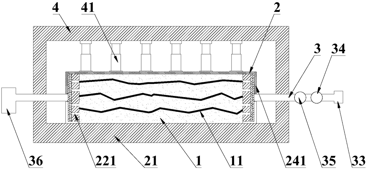
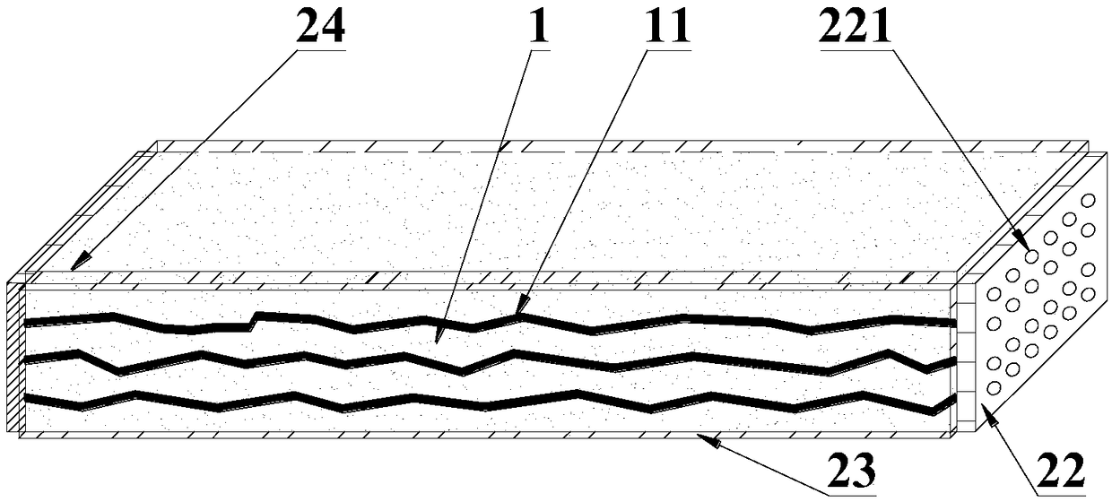
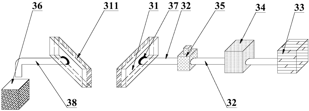
[0025] like figure 1 As shown, a three-dimensional unsteady grouting test device includes a fixing and loading system 2 that closes and accommodates a rock mass sample 1, and a grouting system 3 that cooperates with the fixing and loading system 2 to provide grout for the rock mass sample 1 The rock mass sample 1 has a crack 11, and the fixing and loading system 2 can directly observe the internal rock mass sample 1. The grouting system 3 provides grout for the rock mass sample 1 fixed in the fixing and loading system 2, and the grout flows along the crack 11, and the grouting flow process of the grout can be directly observed through the fixing and loading system 2, which is convenient for obtaining the grout Diffusion ...


PUM

PropertyMeasurementUnit
thicknessaaaaaaaaaa
thicknessaaaaaaaaaa

Abstract

The invention discloses a three-dimensional unsteady slurry grouting test device. The three-dimensional unsteady slurry grouting test device comprises a fixing and loading system for accommodating a rock mass sample in a closing mode and a grouting system, wherein the grouting system is matched with the fixing and loading system and provides slurry for the rock mass sample. The rock mass sample isprovided with cracks, and the internal rock mass sample can be directly observed by the fixing and loading system. The invention further provides a method of observing the three-dimensional unsteadyslurry grouting process. The three-dimensional unsteady slurry grouting test device and the method of observing the three-dimensional unsteady slurry grouting process have the advantages of simple structure, convenient assembly, convenient direct observation of slurry flow characteristics and good promotion prospects.

Description

technical field [0001] The invention relates to the technical field of grout flow diffusion law test, in particular to a three-dimensional unsteady grout injection test device and method. Background technique [0002] In the construction of mines and underground engineering through unfavorable strata, grouting is an effective technology to strengthen the surrounding rock mass and seal off groundwater. The grouting material is injected into the rock-soil medium to achieve the purposes of filling, reinforcement, and water blocking. At present, most of the researches on grouting theory and grouting test assume that parameters such as grout performance parameters (viscosity coefficient, dehydration solidification) and crack shape parameters are constant, and the cracks in the actual engineering surrounding rock mass are simplified to a single smooth shape However, the research on the law of seepage and diffusion of grout cannot truly reflect the changes in grout parameters cause...

Claims


Application Information

Patent Timeline
Patent Type & Authority Applications(China)
IPC IPC(8): G01N3/12
CPCG01N3/12G01N2203/0256
Inventor 孟庆彬韩立军田茂霖金煜皓朱合轩
Owner CHINA UNIV OF MINING & TECH
Why Eureka
Try Eureka