Method for comparison test of thermal performance of two walls and test device

A thermal performance and two-wall technology, which is applied in the thermal performance test device of the wall and the thermal performance comparison test field of the two walls, can solve problems such as inability to test at the same time, constraints of new walls, etc., and achieve low manufacturing cost and improved The effect of accuracy and easy installation

Inactive Publication Date: 2019-01-11
CHINA UNIV OF MINING & TECH +1
View PDF4 Cites 15 Cited by
  • Summary
  • Abstract
  • Description
  • Claims
  • Application Information

AI Technical Summary

Problems solved by technology

[0003] With the continuous development of building energy-saving technology, new types of walls such as phase change walls and thermal insulation composite walls emerge in endlessly, and their thermal performance needs to be evaluated. Most of the existing test devices use heat flow meter method, hot box method, and hot box- Heat flow meter method, constant power planar heat source method, and infrared thermal imager method, etc., but these methods are mostly aimed at the same wall, testing heat transfer coefficient, thermal resistance and other indicators under stable heat transfer conditions, and cannot be used between different walls. Simultaneous testing between
With the continuous emergence of new types of walls, it is often necessary to compare and analyze the thermal performance of different walls in the process of promotion, so as to compare the advantages and disadvantages of thermal performance between different walls. There are certain restrictions on the promotion of the wall

Method used


Image

  • Method for comparison test of thermal performance of two walls and test device
  • Method for comparison test of thermal performance of two walls and test device
  • Method for comparison test of thermal performance of two walls and test device

Examples


Embodiment Construction

[0038] The present invention will be described in detail below in conjunction with the accompanying drawings and specific embodiments.

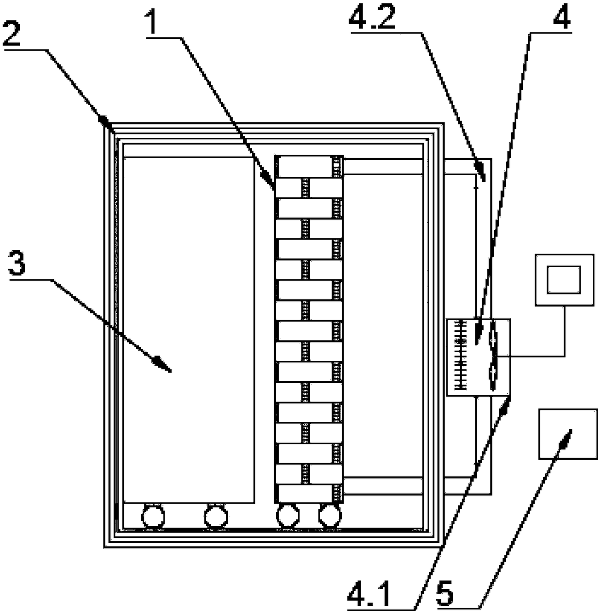
[0039] A test device used in a method for comparing the thermal performance of two walls, including a rectangular test frame 1, a sealed box 2, a constant temperature device 3, a temperature changing device 4 and a data acquisition device 5, the two sides are completely the same in size and different in performance The walls are arranged in a rectangular test frame, the test frame 1 and the constant temperature device 3 for fixing two walls are arranged inside the sealed box, and the temperature changing device 4 and the data acquisition device are arranged outside the sealed box;

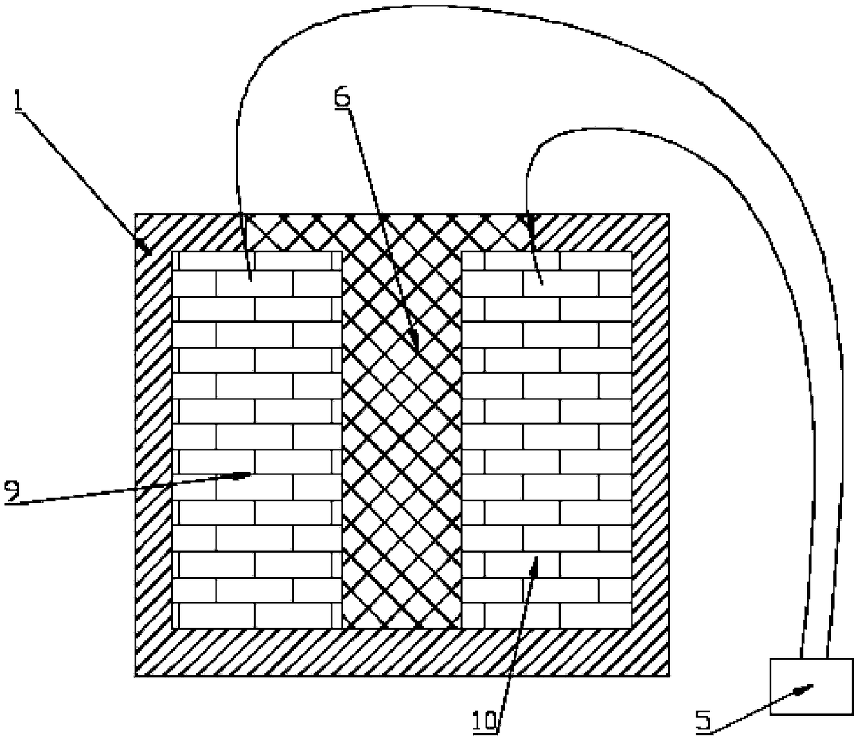
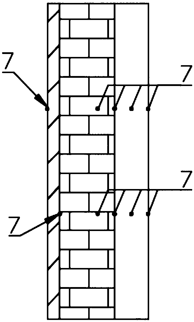
[0040]An XPS insulation board 6 is arranged between the two walls, and the temperature sensor 7 is preset on the inner layer and the surface of the wall during the wall stacking process. Both the sensor 7 and the heat flow sensor 8 are connected to the data acquis...


PUM


Abstract

The invention discloses a method for comparison test of thermal performance of two walls and a test device. The test device comprises a test frame, two walls with different properties, temperature sensors, heat flow sensors and a data collecting and recording terminal. The method comprises the steps of collecting parameters of internal temperature distribution and surface heat flow transfer and the like under same heat transfer boundary conditions, of the two walls with different properties in the test frame, by utilizing the temperature sensors and the heat flow sensors; and carrying out comparative analysis on difference between the two walls on the aspects of the attenuation and the delay of temperature waves, heat transfer coefficient thermal performance parameters according to test data, wherein by applying the alternating temperature waves, specific values of the attenuation coefficients and the delay time of the two test walls can also be obtained respectively under periodic boundary conditions. The method disclosed by the invention has the advantages that not only can the advantages and the disadvantages of the thermal performance of the two walls be directly compared, butalso the test error can be reduced and the accuracy of the comparative analysis is improved. The device has the advantages of being simple in structure, low in manufacturing cost and convenient to install.

Description

technical field [0001] The invention relates to a thermal performance testing device of a wall, in particular to a method and a testing device for comparing the thermal performance of two walls, and belongs to the technical field of thermal performance testing of building walls. Background technique [0002] The shortage of energy and resources has become an important bottleneck restricting the sustainable development of society, and the energy consumption of buildings in my country accounts for about 28% of the total energy consumption of the society. With the development of urbanization and the improvement of people's living standards, the energy consumption of buildings is still increasing rapidly . About 60% of building energy consumption is heating and air-conditioning energy consumption, among which, the heat consumption of envelope structure accounts for more than 1 / 3 of building heating and air-conditioning energy consumption. If the building wall has good thermal in...

Claims


Application Information

Patent Timeline
Patent Type & Authority Applications(China)
IPC IPC(8): G01N25/20
CPCG01N25/20
Inventor 黄建恩吕恒林冯伟马全明刘朋田国华
Owner CHINA UNIV OF MINING & TECH
Why Eureka
Try Eureka