Laser radar optical system and laser radar

A laser radar and optical system technology, applied in the field of detection, can solve the problems of increasing the length, reducing the ranging ability of the lidar, and increasing the divergence angle.

Pending Publication Date: 2019-01-11
SUTENG INNOVATION TECH CO LTD
View PDF0 Cites 9 Cited by
  • Summary
  • Abstract
  • Description
  • Claims
  • Application Information

AI Technical Summary

Problems solved by technology

[0003] Rotary multi-line laser radar is a kind of laser radar. Most of its outer covers are in the shape of a cylinder or a cone. The light in the outer cover will produce optical astigmatism, which will cause the horizontal divergence angle of the laser emitted by the lidar to increase, which will increase the length of the received laser spot in the horizontal direction and reduce the distance measurement capability of the lidar.
[0004] In the prior art, there is no effective method to correct the above errors

Method used


Image

  • Laser radar optical system and laser radar
  • Laser radar optical system and laser radar
  • Laser radar optical system and laser radar

Examples


Embodiment Construction

[0033] The following embodiments of the present invention provide a laser radar optical system and a laser radar, which can reduce the influence of the laser radar casing on the emitted laser light, thereby improving the ranging capability of the laser radar.

[0034] The technical solutions in the embodiments of the present invention will be clearly and completely described below in conjunction with the accompanying drawings in the embodiments of the present invention. Obviously, the described embodiments are only some, not all, embodiments of the present invention. Based on the embodiments of the present invention, all other embodiments obtained by persons of ordinary skill in the art without creative efforts fall within the protection scope of the present invention.

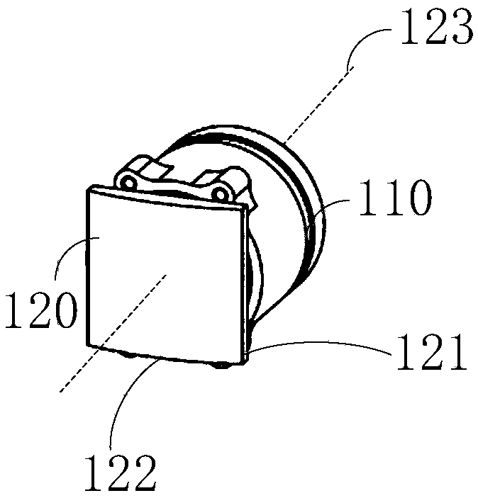
[0035] figure 1 Shown is the schematic diagram of the lidar optical system of the embodiment of the present invention, as figure 1 As shown, the system includes:

[0036] The optical unit 110 at the transmit...


PUM


Abstract

The embodiment of the invention discloses a laser radar optical system and a laser radar. The system comprises a transmitter optical unit and a transmitter correction unit; the transmitter optical unit is used for collimating outgoing laser; the transmitter correction unit comprises at least one transmitter cylindrical lens, and is used for correcting the outgoing laser, wherein the bus of the transmitter cylindrical lens is vertical to the directrix of the transmitter cylindrical lens; the directrix of the transmitter cylindrical lens is parallel to the horizontal plane; the symmetrical axisof the transmitter cylindrical lens is superposed with the optical axis of the transmitter optical unit; the transmitter cylindrical lens comprises a first curved surface and a second curved surface;and outgoing light passes through the transmitter optical unit, the first curved surface of the transmitter cylindrical lens and the second curved surface of the transmitter cylindrical lens in sequence. In the embodiment of the invention, an optical correction unit is arranged at the transmitter; influence of the shell of the laser radar to the outgoing laser can be reduced; and thus, the rangingcapability of the laser radar is improved.

Description

technical field [0001] The invention relates to the detection field, in particular to a laser radar optical system and a laser radar. Background technique [0002] Lidar is a radar system that emits laser beams to detect the position, speed and other characteristic quantities of the target. Its working principle is to first transmit the detection laser beam to the target, and then compare the received signal reflected from the target with the transmitted signal. After proper processing, the relevant information of the target can be obtained, such as target distance, azimuth, height, speed, attitude, and even shape and other parameters. [0003] Rotary multi-line laser radar is a kind of laser radar. Most of its outer covers are in the shape of a cylinder or a cone. The light in the outer cover will produce optical astigmatism, which will cause the horizontal divergence angle of the laser emitted by the lidar to increase, which will increase the length of the received laser ...

Claims


Application Information

Patent Timeline
Patent Type & Authority Applications(China)
IPC IPC(8): G01S7/481
CPCG01S7/4814G01S7/4816
Inventor 邱纯鑫刘乐天
Owner SUTENG INNOVATION TECH CO LTD
Why Eureka
Try Eureka