A composite material laminate I-type delamination simulation method based on cohesive element superposition

A technology of composite material layer and simulation method, which is applied in the field of simulation of type I delamination of composite material laminates, can solve the problems of accurate simulation of type I delamination behavior of composite materials, calculation non-convergence, etc., and achieve the effect of shortening the development cycle

Active Publication Date: 2019-01-11
AVIC BEIJING INST OF AERONAUTICAL MATERIALS
View PDF2 Cites 9 Cited by
  • Summary
  • Abstract
  • Description
  • Claims
  • Application Information

AI Technical Summary

Problems solved by technology

This method requires the development of user subroutines that can be embedded in finite element software modules, which puts forward high technical requirements for engineers. In addition, user-defined subroutines are often difficult t

Method used


Image

  • A composite material laminate I-type delamination simulation method based on cohesive element superposition
  • A composite material laminate I-type delamination simulation method based on cohesive element superposition
  • A composite material laminate I-type delamination simulation method based on cohesive element superposition

Examples


Example Embodiment

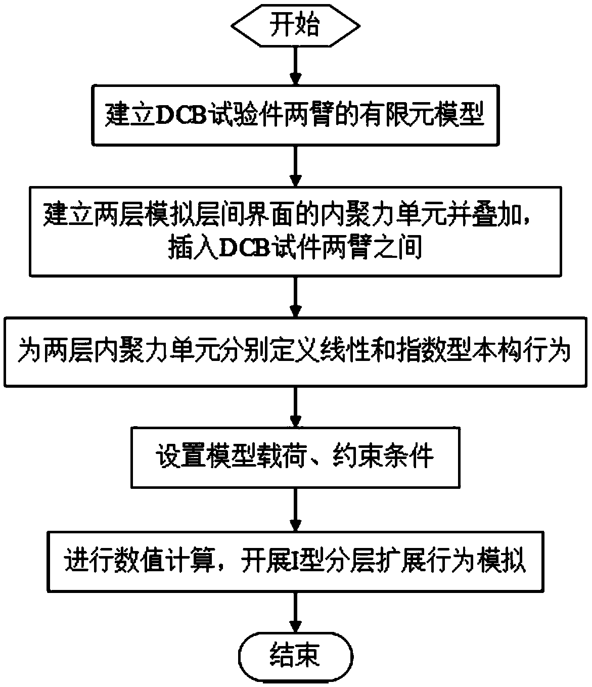
[0038] The specific embodiment of the present invention will be further described below with an example of a type I layered DCB test of a composite material laminate. This example is only used to explain and illustrate the present invention, and does not constitute any limitation to the present invention.

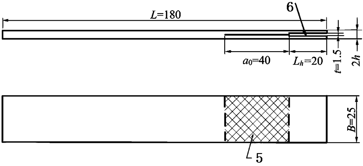
[0039] geometric description;

[0040] The configuration and geometric dimensions of the actual DCB test piece are as follows figure 2 Shown, where h is the thickness of the upper and lower arms of the test piece, and B is the width of the test piece. Among them, the upper arm and the lower arm of the DCB test piece are laminated in the order of [90° / 0° 10 / 90°] composite multi-directional laminate, wherein the average thickness of each composite single layer is 0.185mm. In the layering stage of the laminates of the test piece, a layer of PTFE film with a length of 40mm is embedded between the two adjacent layers of the upper arm 1 and lower arm 2 layers to obtain a 90° / ...


PUM

PropertyMeasurementUnit
Thicknessaaaaaaaaaa

Abstract

The invention relates to a composite material laminate I-type delamination simulation method based on cohesive element superposition, comprising the following steps: (1) utilizing finite element software ABAQUS to establish three-dimensional finite element models of upper arm 1 and lower arm 2 of a double-cantilever beam (hereinafter referred to as DCB) test piece of the composite material laminate; (2) at the interface between the three-dimensional finite element models of the upper arm 1 and the lower arm 2 of the DCB test piece, establishing two layers of cohesive elements, wherein one layer of cohesive elements is provided with a linear cohesive force constitutive model, and the other layer of cohesive elements is provided with an exponential cohesive force constitutive model; (3) according to the load state of the actual DCB test, the corresponding load and constraint conditions are set for the three-dimensional finite element model; (4) carrying out the numerical simulation of I-delamination behavior in composite laminates by using the finite element software ABAQUS, and obtaining the load-displacement curve in the process of simulation test is obtained. The method of the invention can accurately predict the I-type delamination expansion resistance behavior of the composite multidirectional laminates without self-defining cohesive constitutive relation, is convenient, fast, suitable for engineering application, and can effectively guide the design and analysis of the composite structure. The invention is characterized in that the method of the invention can accuratelypredict the I-type delamination expansion resistance behavior of the composite multidirectional laminates.

Description

technical field [0001] The invention relates to a method for simulating type I delamination of composite material laminates based on the superposition of cohesive units, and belongs to the technical field of numerical simulation of composite material structure damage behavior. Background technique [0002] Continuous fiber reinforced composites are increasingly widely used in the aerospace field because of their excellent mechanical properties such as high specific strength and specific stiffness, tailorable design, and good fatigue performance. With the continuous accumulation and development of composite material manufacturing technology and composite material structure design, analysis and application technology, the amount of composite material laminates in military aircraft and civil aircraft structures has gradually increased, and the application parts have gradually developed from secondary load-bearing structures to load-bearing structures. The main load-bearing stru...

Claims


Application Information

Patent Timeline
IPC IPC(8): G06F17/50
CPCG06F30/23
Inventor 王雅娜王翔
Owner AVIC BEIJING INST OF AERONAUTICAL MATERIALS
Why Eureka
Try Eureka