Real-time infrared target detection system and method based on FPGA
A real-time detection technology for infrared targets, which is applied to TV system components, color TV components, details related to image processing hardware, etc., can solve the problems of DSP and FPGA performance waste and low efficiency of infrared target detection, and achieve Effects of reducing delay time, increasing image processing speed, and improving computing efficiency
- Summary
- Abstract
- Description
- Claims
- Application Information
AI Technical Summary
Problems solved by technology
Method used
Image
Examples
Embodiment 1
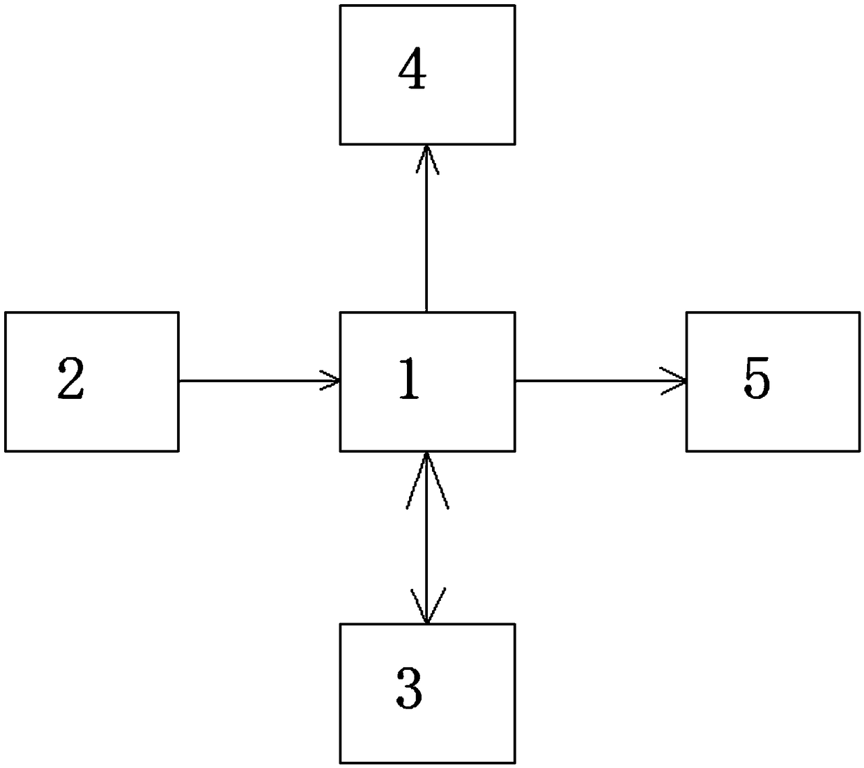
[0057] Such as figure 1 As shown, a real-time detection system for infrared targets based on FPGA of the present invention includes:
[0058] An infrared camera device, which is used to collect infrared images and process the infrared images into image data that can be transmitted;
[0059] FPGA module, the FPGA module communicates with the infrared camera device, and the FPGA module receives image data and extracts information on the position and shape of the infrared target in parallel processing;
[0060] Two-dimensional servo pan / tilt, the two-dimensional servo pan / tilt is connected to the FPGA module in communication, the two-dimensional servo pan / tilt and the FPGA module cooperate to perform closed-loop feedback control on the information of the infrared target position and shape; namely: the two-dimensional servo pan / tilt and the FPGA module Cooperate to identify the position and shape of the infrared target and control the infrared camera device to follow the infrared target ...
Embodiment 2
[0065] An infrared detection method of an infrared target real-time detection system based on FPGA includes the following steps:
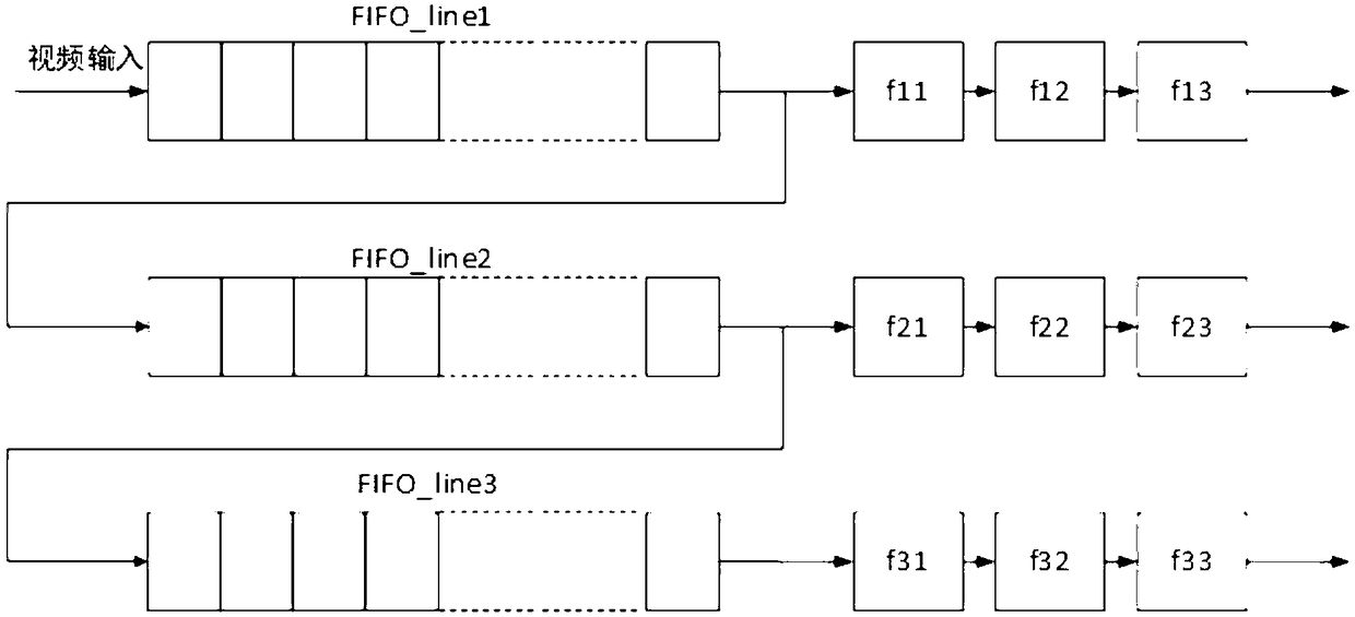
[0066] Edge detection steps: under the beat of the image clock, the image is buffered into the FIFO, and the image gray values of 3 lines are stored in the FPGA through 3 FIFO buffers, and then the data of the FIFO are read out and registered with 3 registers Data, get 9 data (f11-f33), and then calculate the edge according to the following formula to get the gradient image;
[0067] f”(x,y)=|f(x+1,y)+f(x-1,y)-2f(x,y)|+|f(x,y+1)+f(x,y) -1)-2f(x,y)|
[0068] Among them, f(x, y) is the gray value of the image at the (x, y) coordinates;
[0069] f” (x, y) is the edge detection value at (x, y) coordinates.
[0070] The advantage of the above steps is that the design idea of this module makes full use of the parallel design and pipeline processing ideas of FPGA. Under the beat of the image clock, the image is buffered into the FIFO step by step. When the im...
PUM
 Abstract
Description
Claims
Application Information
 - R&D
- Intellectual Property
- Life Sciences
- Materials
- Tech Scout
- Unparalleled Data Quality
- Higher Quality Content
- 60% Fewer Hallucinations
Browse by: Latest US Patents, China's latest patents, Technical Efficacy Thesaurus, Application Domain, Technology Topic, Popular Technical Reports.
© 2025 PatSnap. All rights reserved.Legal|Privacy policy|Modern Slavery Act Transparency Statement|Sitemap|About US| Contact US: help@patsnap.com


