
Magnetic closed ignition coil

An ignition coil, closed magnetic technology, applied in the direction of transformer/inductor coil/winding/connection, transformer/inductor core, transformer, etc., can solve the problems of affecting engine power, insufficient secondary ignition energy, etc., to achieve ignition Reliable and stable, improved performance, full combustion effect

Pending Publication Date: 2019-01-11
嘉兴德科发动机部件有限公司
View PDF0 Cites 4 Cited by
  • Summary
  • Abstract
  • Description
  • Claims
  • Application Information

AI Technical Summary

Problems solved by technology

[0003] However, the existing ignition coils often adopt an open-loop iron core structure, resulting in insufficient secondary ignition energy, which affects the power of the engine. However, due to the limitation of the volume of the ignition coil, it is impossible to improve the secondary voltage by increasing the iron core or winding of the ignition coil. to improve ignition energy

Method used


Image

  • Magnetic closed ignition coil
  • Magnetic closed ignition coil
  • Magnetic closed ignition coil

Examples


Embodiment Construction

[0034] In order to make the purpose, technical solutions and advantages of the present application clearer, the technical solutions in the embodiments will be clearly and completely described below in conjunction with the accompanying drawings in the embodiments,

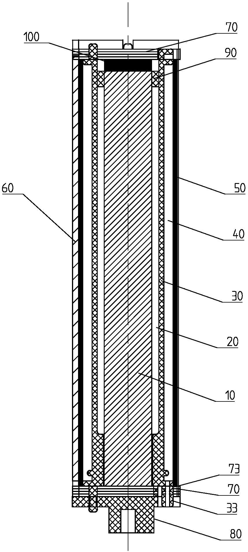
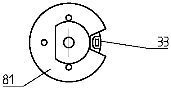
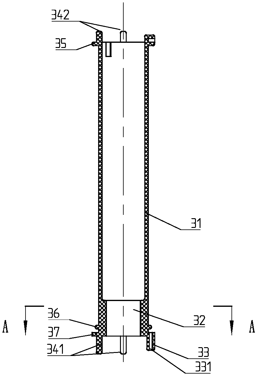
[0035] A closed magnetic ignition coil, comprising an iron core 10, a primary winding 20 wound on the peripheral surface of the iron core 10 and arranged axially, a high-voltage bobbin 30 sleeved outside the primary winding 20, and wound on the high-voltage bobbin 30 The secondary winding 40, the ceramic sleeve 60 set on the secondary winding 40, the two ends of the ceramic sleeve 60 are fitted with a magnetically conductive cover 70 and the two ends of the iron core 10 are attached to the two magnetically conductive covers 70, form a closed magnetic circuit.

[0036] A magnetic steel 100 is clamped between one end of the iron core 10 and the magnetically permeable cover 70 at the corresponding end, and the magnetic...


PUM


Abstract

A magnetic closed ignition coil disclosed in the invention includes iron core, a primary winding wound around the periphery of the core and arranged axially, a high voltage skeleton sleeved over the primary winding, a secondary winding wound on a high voltage skeleton, a ceramic conductive sleeve sleeved on the secondary winding and a housing enclosing the above-mentioned components, characterizedin that: a magnetic conductive cov is fixed on both end surface of that porcelain conductive sleeve and the two end surfaces of the iron core are bonded with the two magnetic conductive covers, so that a closed magnetic circuit is for, Increase core flux, so as to obtain more ignition energy at the output end of the same volume pen rod coil, a magnetic steel is clam between one end of that iron core and the magnetic conductive cover at the correspond end, and the magnetic circuit is not saturated due to the magnetic bias. The ceramic conductive sleeve is open-loop, and the open-loop is necessary, otherwise, the primary short circuit is equivalent, and the open-loop can also insulate the high-voltage output end from the magnetic conductive sleeve by a sufficient distance.

Description

technical field [0001] The invention belongs to the technical field of ignition coils, in particular to a closed magnet ignition coil. Background technique [0002] As a main means of transportation, automobiles are indispensable in people's daily work and life in today's society. With the continuous development and updating of the automobile industry, most of the ignition coils used in cars today have been changed to a pen holder structure. This type of ignition coil is directly connected to the spark plug through a rubber sheath. The product is small in size and has strong electromagnetic compatibility. , high output voltage and higher combustion efficiency are the development trend of ignition coils. [0003] However, the existing ignition coils often adopt an open-loop iron core structure, resulting in insufficient secondary ignition energy, which affects the engine power. However, due to the limitation of the volume of the ignition coil, it is impossible to improve the...

Claims


Application Information

Patent Timeline
Patent Type & Authority Applications(China)
IPC IPC(8): H01F38/12H01F27/24H01F27/245H01F27/26H01F27/29H01F27/30
CPCH01F27/24H01F27/2455H01F27/263H01F27/29H01F27/306H01F38/12
Inventor 吴飞吴昊
Owner 嘉兴德科发动机部件有限公司
Learn More