An automatic lifting energy-saving moisture-proof power distribution cabinet

A lift-type, power distribution cabinet technology, applied in the direction of substation/distribution device casing, etc., can solve the problems of easy aging of internal circuits, affect safety, affect heat dissipation, etc., and achieve high efficiency to ensure internal drying and prevent dust and impurities from entering. Effect

Active Publication Date: 2020-04-28
HEBEI INST OF MACHINERY ELECTRICITY
View PDF22 Cites 0 Cited by
  • Summary
  • Abstract
  • Description
  • Claims
  • Application Information

AI Technical Summary

Problems solved by technology

[0002] Power distribution cabinets and control cabinets need to be used in various environments, and the smoke and dust in many environments are conductive. Once the humidity inside the device is too high, the inside is extremely easy to rust, and the internal circuit is easy to age and short circuit. will greatly affect the security
[0003] In the prior art, the humidity control is mainly carried out during the air intake, which will cause a huge consumption of desiccant, and if it is closed during drying, it will affect the heat dissipation

Method used


Image

  • An automatic lifting energy-saving moisture-proof power distribution cabinet
  • An automatic lifting energy-saving moisture-proof power distribution cabinet
  • An automatic lifting energy-saving moisture-proof power distribution cabinet

Examples


Embodiment 2

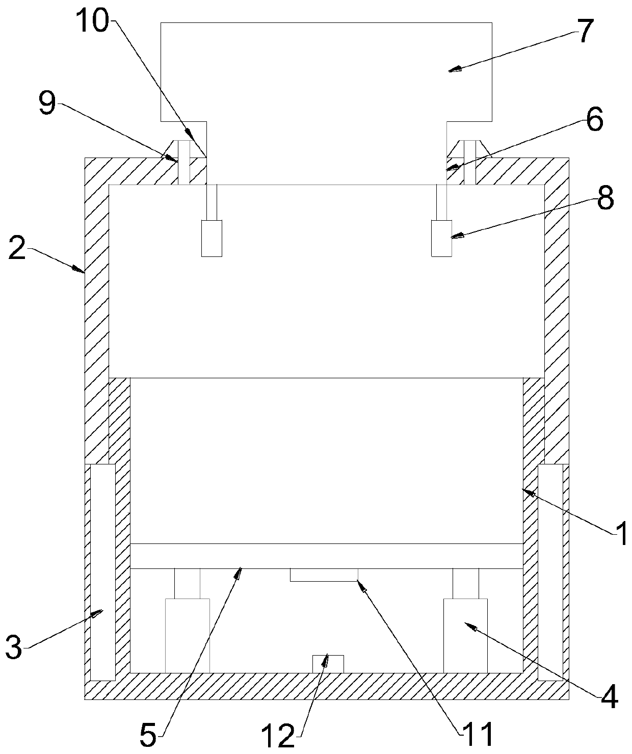
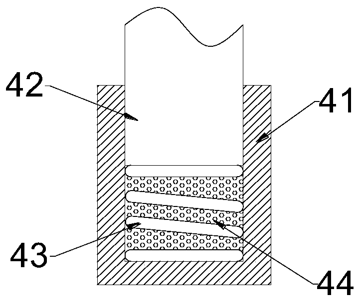
[0026] see image 3 , in the embodiment of the present invention, an automatic lifting type energy-saving and moisture-proof power distribution cabinet, on the basis of embodiment 1, the telescopic support rod 4 is composed of a sleeve 41, a sliding rod 42 and a spring 43, and the sleeve 41 It is connected with the sliding rod 42 through a sliding socket, the bottom of the sliding rod 42 is elastically connected with the inner bottom of the sleeve 41 through a spring 43, and the lower end of the sliding rod 42 is connected to the inner bottom of the sleeve 41. The cavities are filled with crushed foam 44 .

[0027] The working principle of the present invention is: when in use, the first electric telescopic rod 3 is driven up and down to control the installation of equipment on the placement plate 5. When the equipment is running, the telescopic support rod 4 can be used for efficient vibration reduction. At the same time, the lower casing 1 and the upper casing The assembly ...


PUM


Abstract

The invention discloses an automatic lifting energy-saving moisture-proof distribution cabinet, including a lower house, Upper case, drying head, humidity sensors and PLC controllers, at both side ofthat lower house, the upper housing is movably clamped by a first electric telescopic rod, an upper end of that low housing is connected with a drying head movably assembled with the through hole through a second electric telescopic push rod. The drying head is provided with an air inlet and an exhaust structure, the air flow of the drying head enters the lower housing through the first air inlethole and is discharged through the drying head when the drying head is raised, the first air inlet hole is blocked when the drying head is lowered, and the air flow is sucked through the air inlet structure of the drying head and is discharged from the exhaust structure. As that humidity sensor sense a higher humidity in the low housing. The second electric telescopic push rod drives the drying head down, the first air inlet hole is blocked, the air flow enters through the upper end of the second air inlet hole and dries under the action of the desiccant when the fan is driven, enters the lower shell and is discharged through the exhaust hole, so that the internal drying can be efficiently ensured on the basis of ensuring heat dissipation.

Description

technical field [0001] The invention relates to an electric automatic power distribution cabinet, in particular to an automatic lifting type energy-saving and moisture-proof power distribution cabinet. Background technique [0002] Power distribution cabinets and control cabinets need to be used in various environments, and the smoke and dust in many environments are conductive. Once the humidity inside the device is too high, the inside is extremely easy to rust, and the internal circuit is easy to age and short circuit. It will greatly affect security. [0003] In the prior art, the humidity control is mainly carried out during the air intake, which will cause a huge consumption of desiccant, and if the drying process is closed, it will affect the heat dissipation. Contents of the invention [0004] The object of the present invention is to provide an automatic lift-type energy-saving and moisture-proof power distribution cabinet to solve the problems raised in the abov...

Claims


Application Information

Patent Timeline
Patent Type & Authority Patents(China)
IPC IPC(8): H02B1/30H02B1/28
CPCH02B1/28H02B1/30
Inventor 崔嵬方红彬郭少卿
Owner HEBEI INST OF MACHINERY ELECTRICITY
Why Eureka
Try Eureka