A peeling device for cable processing

A cable and bottom plate technology, which is applied in the field of stripping devices for cable processing, can solve the problems of cable stripping without setting springs, and does not take into account the easy wear and break of the blade, so as to increase practicability and solve the effects of easy wear and break

Inactive Publication Date: 2019-01-11
马爱华
View PDF1 Cites 2 Cited by
  • Summary
  • Abstract
  • Description
  • Claims
  • Application Information

AI Technical Summary

Problems solved by technology

[0004] In the above-mentioned patent, although multiple blades are set on the reinforcing block to realize the peeling of the cables, it does not take into account that the blades are easy to wear and break, and no spring is set to realize the peeling of cables of different thicknesses.

Method used


Image

  • A peeling device for cable processing
  • A peeling device for cable processing
  • A peeling device for cable processing

Examples


Embodiment 1

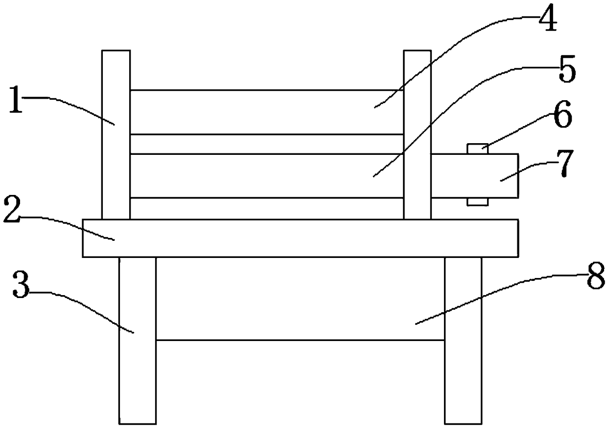
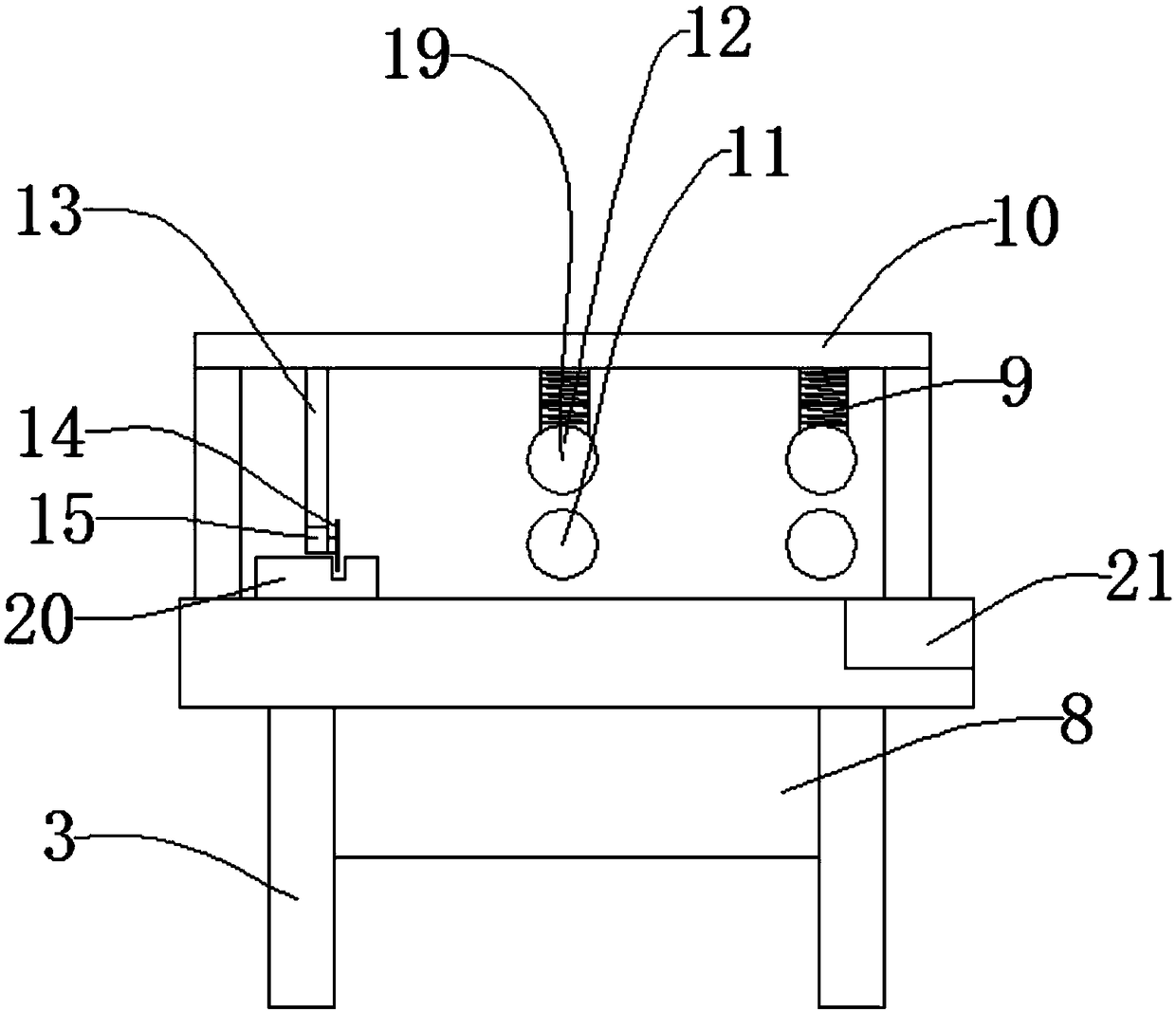
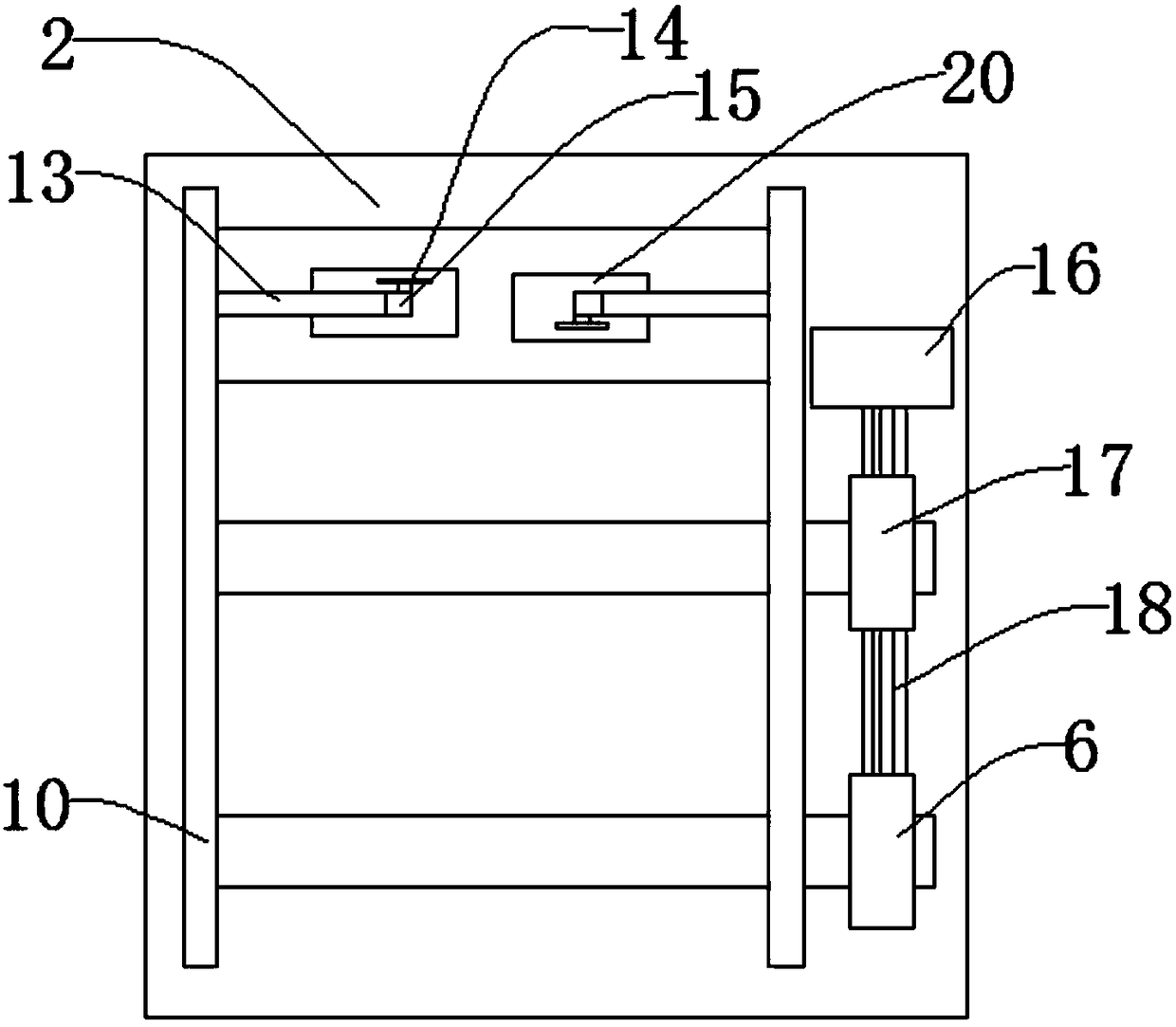
[0028] Such as Figure 1-Figure 4 As shown, a stripping device for cable processing includes a base plate 2, a first spring 9, and a control panel 21, the front portion of the base plate 2 is provided with a control panel 21, the lower part of the base plate 2 is provided with a control box 8, and the control box 8 is provided around There are support legs 3, and the support legs 3 are used to support the whole device. The upper part of the base plate 2 is provided with a support plate 1, and the top of the support plate 1 is provided with a support rod 10. The lower part of the support rod 10 is provided with a first spring 9, and the first spring 9 is used for Adjust the distance between the upper roller knife 4 and the lower hob 5. The lower part of the first spring 9 is provided with an upper hob 4. The upper hob 4 is used to cut off the outer skin of the cable. The lower part of the upper hob 4 is provided with a lower hob 5. The lower hob 5 is used to cut off the outer s...

Embodiment 2

[0030] The difference between this embodiment and Embodiment 1 is that in this embodiment, the upper hob 4 is connected to the support plate 1 through a bearing, and the lower hob 5 is connected to the support plate 1 through a bearing.

[0031] Specifically, such setting can solve the problem that the blade is easy to wear and break.

[0032] The specific working principle of the present invention is: open the control panel 21, the drive motor 16, the motor 15, and the control box 8 start to work. It is cut open, but the metal wire inside is not separated from the outer skin, and the hob is used to replace the traditional blade for peeling, which solves the problem that the blade is easy to wear and break. The upper hob 4 and the lower hob can be adjusted through the first spring 9. The distance between the hobs 5 realizes the peeling of cables of different thicknesses, which increases the practicability of the device, and then the cables that are cut off will enter between t...


PUM


Abstract

The invention discloses a peeling device for cable processing, Including bottom plate, First spring, Control Panel, a control panel is arranged at the front of the bottom plate, a low part of that bottom plate is provided with a control box, a support leg is arranged around that control box, a support plate is arranged on that upper part of the bottom plate, a support bar is arranged at that top of the support plate, a low part of that support rod is provided with a first spr, an upper hob is arranged at the lower part of the first spring, a low hob is arranged at the lower part of the upper hob, a connecting shaft is arranged at one side of the lower hob, a second driven wheel is arranged on the connecting shaft, a belt is arranged on the second driven wheel, and a second spring is arranged at one side of the first spring. The invention has the advantages that: 1, the hob is used for peeling instead of the traditional blade, and the problem of easy wear and break of the blade is solved; 2, a spring is arrange, that peeling of the cable with different thicknesses is realized, and the practicability of the device is increase.

Description

technical field [0001] The invention relates to the technical field of power cable processing, in particular to a stripping device for cable processing. Background technique [0002] It is usually a rope-like cable twisted by several or groups of wires (at least two in each group), each group of wires is insulated from each other, and is often twisted around a center, and the entire outer surface is covered with a high degree of insulation overlay. Cables have the characteristics of internal electrification and external insulation. Cables include power cables, control cables, compensation cables, shielded cables, high-temperature cables, computer cables, signal cables, coaxial cables, fire-resistant cables, marine cables, mine cables, and aluminum alloy cables. etc., they are composed of single-strand or multi-strand wires and insulating layers, used to connect circuits, electrical appliances, etc. According to different uses and usage environments, they can be divided into...

Claims


Application Information

Patent Timeline
IPC IPC(8): H02G1/12
CPCH02G1/1256
Inventor 马爱华
Owner 马爱华
Why Eureka
Try Eureka